Imaging lens element, camera module and electronic device

Inactive Publication Date: 2019-01-10
LARGAN PRECISION
View PDF3 Cites 1 Cited by
  • Summary
  • Abstract
  • Description
  • Claims
  • Application Information

AI Technical Summary

Benefits of technology

The present invention provides an imaging lens element with a unique structure that includes an effective optical section and an outer diameter section. The outer diameter section has an outer diameter curved surface, a withdrawn gate trace, and a clearance surface. The withdrawn gate trace is a curved surface that is withdrawn from the outer diameter reference plane towards the optical axis. The outer diameter curved surface and the effective optical section are coaxial with the optical axis. The clearance surface connects the outer diameter curved surface and the withdrawn gate trace. The outer diameter curved surface is closer to the optical axis than the withdrawn gate trace is to the optical axis. The present invention also provides a camera module and an electronic device that includes the imaging lens element.

Problems solved by technology

Therefore, the intensity of the reflection light which is incident to the outer diameter section cannot be effectively attenuated, especially for the case when the outer diameter section is disposed with a plane, such as the cut trace plane on the cut trace surface.
The injection efficiency parameter Ig of the imaging lens element 8830 in the first prior art is 0.786 mm, which represents that the molding efficiency of the imaging lens element 8830 is unacceptable, and the yield of the imaging lens element 8830 may be unacceptable as well.
Meanwhile, the injection efficiency parameter Ig and the injection coefficient Ic show that the molding quality of the imaging lens element 9930 is unacceptable and the time for molding the imaging lens element 9930 is too long.
Further, when the size of the injecting inlet (which is proportional to the width Wg of the conventional cut trace 9970) of the imaging lens element 9930 is too small, the molding quality of the effective optical section 9940 may be unacceptable as well.
To sum up, the conventional cut trace in the prior arts makes it difficult for the imaging lens element to satisfy the current requirements of the camera modules.

Method used


Image

  • Imaging lens element, camera module and electronic device
  • Imaging lens element, camera module and electronic device
  • Imaging lens element, camera module and electronic device

Examples


1st embodiment

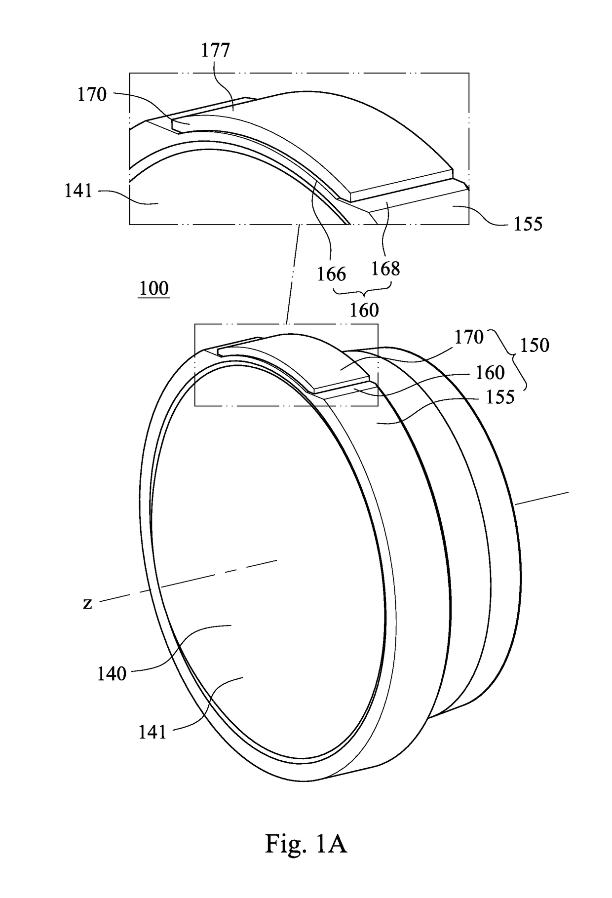
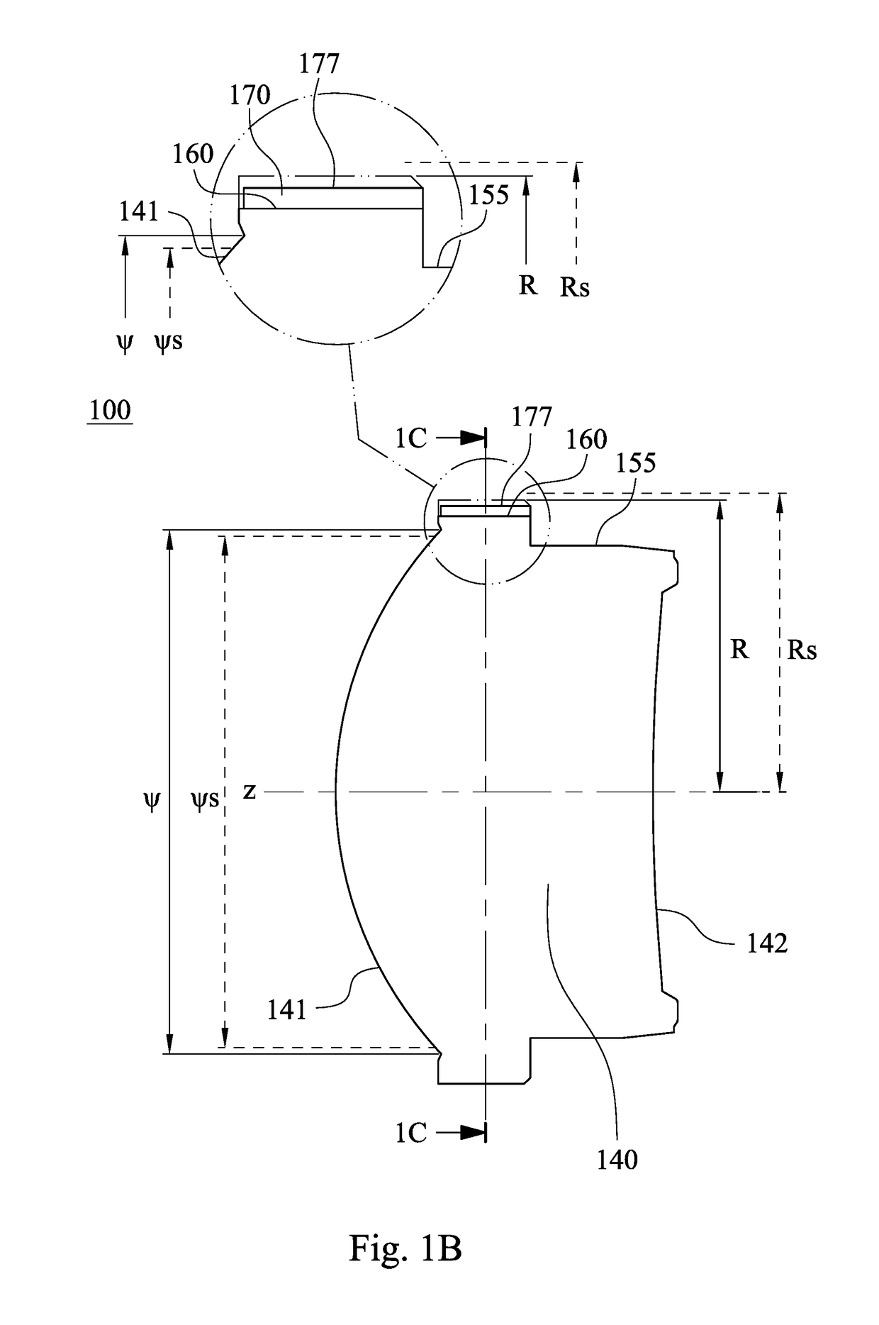
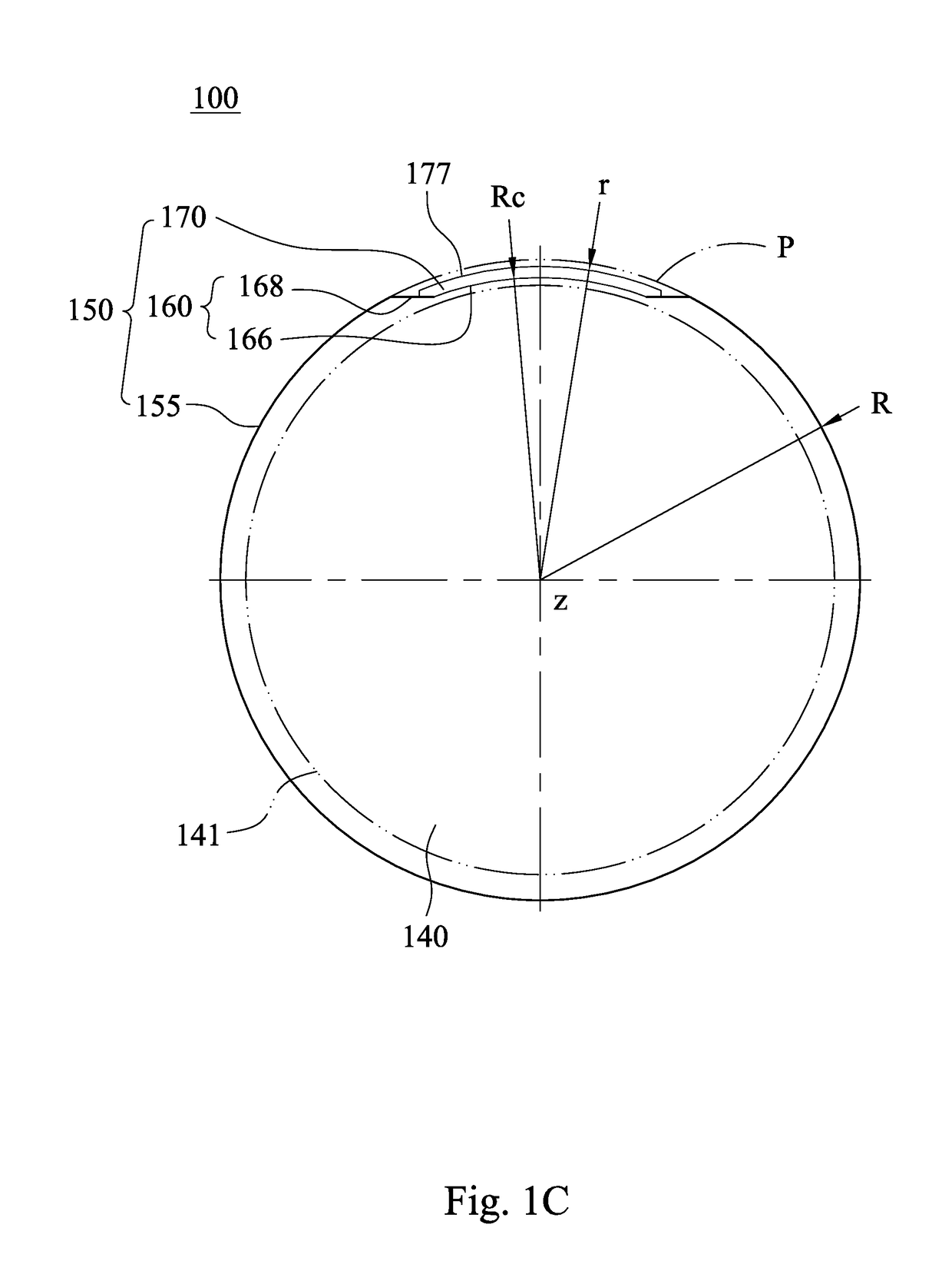
[0040]FIG. 1A is a 3-D view of an imaging lens element 100 of the 1st embodiment of the present disclosure, and FIG. 1B is a front view of the imaging lens element 100 of the 1st embodiment. In FIG. 1A and FIG. 1B, the imaging lens element 100 includes, in order from an optical axis z to a periphery, an effective optical section 140 and an outer diameter section 150.

[0041]In detail, the imaging lens element 100 may be one of a plurality of imaging lens elements in a camera module (not shown), and based on the requirements of the optical imaging and the assembling sizes of the camera module, the optical effective specification (i.e., the minimum diameter of the object-end surface of the effective optical section that can be allowed) that the imaging lens element 100 needs to satisfy is ψs. The height limitation specification that the imaging lens element 100 needs to satisfy is Rs, wherein the height limitation specification represents half of the maximum outer diameter of the imagin...

2nd embodiment

[0061]FIG. 2A is a schematic view of an imaging lens element 200 of the 2nd embodiment of the present disclosure. In FIG. 2A, the imaging lens element 200 includes, in order from an optical axis z to a periphery, an effective optical section 240 and an outer diameter section 250.

[0062]In the 2nd embodiment, the optical effective specification ψs and the height limitation specification Rs that the imaging lens element 200 needs to satisfy are the same as the imaging lens element 100 in the 1st embodiment.

[0063]In addition, other structures of the imaging lens element 200 may be identical to or different from the imaging lens element 100 of the 1st embodiment.

[0064]FIG. 2B is a schematic view of the parameters of FIG. 2A, and FIG. 2C is another schematic view of the parameters of FIG. 2A. The cross-sectional plane mentioned in the 2nd embodiment is any of the cross-sectional planes of the imaging lens element 200 across a withdrawn gate trace 270 and has a normal direction parallel to...

3rd embodiment

[0074]FIG. 3A is a schematic view of an imaging lens element 300 of the 3rd embodiment of the present disclosure. In FIG. 3A, the imaging lens element 300 includes, in order from an optical axis z to a periphery, an effective optical section 340 and an outer diameter section 350.

[0075]In the 3rd embodiment, the optical effective specification ψs and the height limitation specification Rs that the imaging lens element 300 needs to satisfy are the same as the imaging lens element 100 in the 1st embodiment. In addition, other structures of the imaging lens element 300 may be identical to or different from the imaging lens element 100 of the 1st embodiment.

[0076]FIG. 3B is a schematic view of the parameters of FIG. 3A, and FIG. 3C is another schematic view of the parameters of FIG. 3A. The cross-sectional plane mentioned in the 3rd embodiment is any of the cross-sectional planes of the imaging lens element 300 across a withdrawn gate trace 370 and has a normal direction parallel to the ...


PUM

PropertyMeasurementUnit
Fractionaaaaaaaaaa
Fractionaaaaaaaaaa
Fractionaaaaaaaaaa

Abstract

An imaging lens element includes an effective optical section and an outer diameter section. The outer diameter section surrounds the effective optical section and includes an outer diameter curved surface, a withdrawn gate trace and a clearance surface. The outer diameter curved surface and the effective optical section are coaxial with respect to the optical axis. An outer diameter reference plane and the outer diameter curved surface are corresponding to each other with respect to the optical axis. The withdrawn gate trace is withdrawn from the outer diameter reference plane towards the optical axis and includes a gate trace curved surface. The clearance surface connects the outer diameter curved surface and the withdrawn gate trace. On a cross-sectional plane of the imaging lens element, a curvature center of the gate trace curved surface is closer to the optical axis than the gate trace curved surface is thereto.

Description

RELATED APPLICATIONS[0001]This application claims priority to Taiwan Application Serial Number 106122733, filed Jul. 06, 2017, which is herein incorporated by reference.BACKGROUNDTechnical Field[0002]The present disclosure relates to an imaging lens module and a camera module. More particularly, the present disclosure relates to an imaging lens module and a camera module that can be applicable to portable electronic devices.Description of Related Art[0003]Nowadays, the camera modules on portable electronic devices usually include a plurality of imaging lens elements, and the outer diameter section of the imaging lens elements are highly reflective for being smooth and bright, just like the effective optical sections. Therefore, the intensity of the reflection light which is incident to the outer diameter section cannot be effectively attenuated, especially for the case when the outer diameter section is disposed with a plane, such as the cut trace plane on the cut trace surface. In ...

Claims


Application Information

Patent Timeline
IPC IPC(8): G02B13/00G02B1/04G02B7/02
CPCG02B13/002G02B7/02G02B1/041G02B3/02G02B7/021G02B7/022G02B5/003G02B27/0018
Inventor CHANG, MING-SHUNCHOU, MING-TA
Owner LARGAN PRECISION
Why Eureka
Try Eureka