
Antenna module and electronic device including the same

a technology of antenna module and electronic device, applied in the direction of substation equipment, radiating element structure, transportation and packaging, etc., can solve the problems of many obstacles to implementation of smartphone payments, insufficient standardized nfc performance of many smartphones, and universal use of payment methods

Active Publication Date: 2019-01-10
WITS CO LTD
View PDF6 Cites 6 Cited by
  • Summary
  • Abstract
  • Description
  • Claims
  • Application Information

AI Technical Summary

Benefits of technology

The antenna module described in this patent allows for a small space to be taken up while still providing high performance. This results in smaller and thinner electronic devices that use the antenna module.

Problems solved by technology

However, a data transmission channel between point-of-sale (POS) terminals universally installed in stores, or the like, and smartphones, does not exist, resulting in payments using smartphones having many obstacles to implementation.
However, since a reading apparatus appropriate for a POS terminal does not exist, it is difficult to universally use payment methods using a 2D barcode or NFC, and particularly, in a case of NFC, standardized NFC performance is insufficient in many smartphones, and a separate apparatus for reading NFC signals needs to be provided.

Method used


Image

  • Antenna module and electronic device including the same
  • Antenna module and electronic device including the same
  • Antenna module and electronic device including the same

Examples


Embodiment Construction

[0036]The following detailed description is provided to assist the reader in gaining a comprehensive understanding of the methods, apparatuses, and / or systems described herein. However, various changes, modifications, and equivalents of the methods, apparatuses, and / or systems described herein will be apparent after an understanding of the disclosure of this application. For example, the sequences of operations described herein are merely examples, and are not limited to those set forth herein, but may be changed as will be apparent after an understanding of the disclosure of this application, with the exception of operations necessarily occurring in a certain order. Also, descriptions of features that are known in the art may be omitted for increased clarity and conciseness.

[0037]The features described herein may be embodied in different forms, and are not to be construed as being limited to the examples described herein. Rather, the examples described herein have been provided mer...


PUM


Abstract

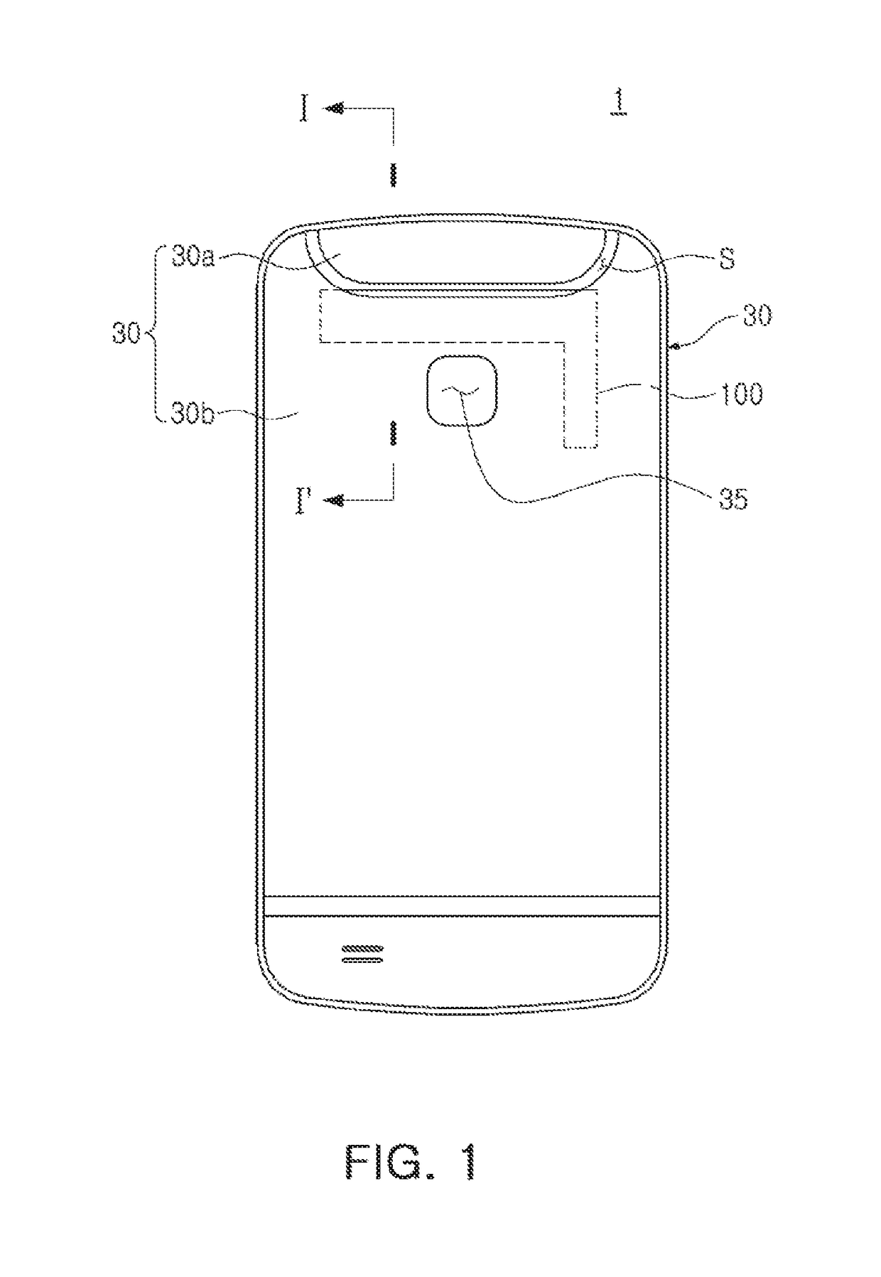
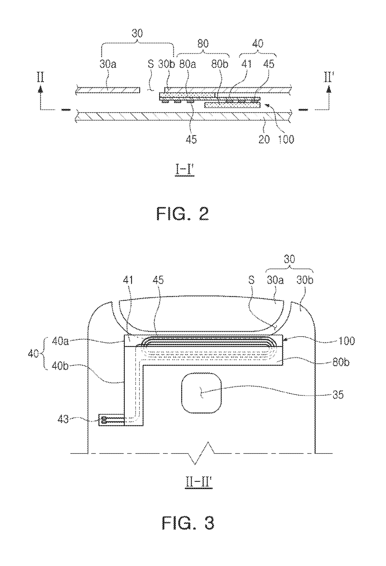
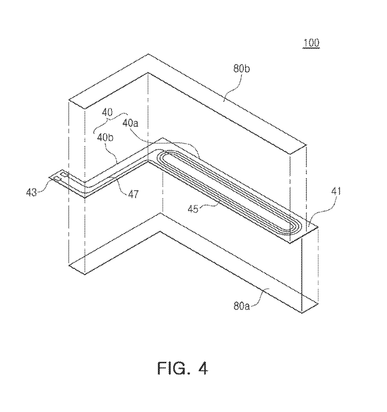
An antenna module disposed inside a conductive cover and performing near field communications includes: a wiring portion having antenna wirings formed on an insulating substrate and having a first surface facing an inner surface of the conductive cover and a second surface opposing the first surface; a first magnetic portion disposed between the first surface of the wiring portion and the conductive cover; and a second magnetic portion disposed on the second surface of the wiring portion, wherein the first magnetic portion and the second magnetic portion are disposed to partially overlap each other or to have edges thereof in vertical correspondence with each other.

Description

CROSS-REFERENCE TO RELATED APPLICATION(S)[0001]This application claims the benefit under 35 USC § 119(a) to Korean Patent Application Nos. 10-2017-0086595 filed on Jul. 7, 2017 and 10-2017-0123377 filed on Sep. 25, 2017 in the Korean Intellectual Property Office, the entire disclosures of each of which are incorporated herein by reference for all purposes.BACKGROUND1. Field[0002]The disclosure relates to an antenna module and an electronic device including the same.2. Description of Related Art[0003]As portable terminals such as smartphones are increasingly universally used, and functions of such portable terminals are improved, a payment method for portable terminals using near field communications has emerged. However, a data transmission channel between point-of-sale (POS) terminals universally installed in stores, or the like, and smartphones, does not exist, resulting in payments using smartphones having many obstacles to implementation. In order to solve such problems, payment...

Claims


Application Information

Patent Timeline
IPC IPC(8): H01Q1/24H01Q1/22H01Q7/00H02J7/02H04M1/02
CPCH01Q1/243H01Q1/2208H04M1/026H02J7/025H01Q7/00H01Q1/38H04B5/26H02J50/20
Inventor WON, JAE SUNCHEON, YOUNG MINKIM, HEE SEUNGJANG, JAE HYUKKWEON, GIE HYOUNLEE, CHANG HEEYIO, SOON JOUNGYOON, HYO JUNG
Owner WITS CO LTD
Learn More