Allocating Reactive Power Production for Doubly Fed Induction Generator Wind Turbine System

a technology of induction generator and reactive power production, which is applied in the direction of wind energy generation, generator control circuit, electric generator control, etc., can solve the problems of reducing the efficiency and operating life of dfig, dfig to wear out at a faster rate, and the statator may be subject to increased stresses

Active Publication Date: 2019-01-10
GENERAL ELECTRIC CO
View PDF5 Cites 5 Cited by
  • Summary
  • Abstract
  • Description
  • Claims
  • Application Information

AI Technical Summary

Benefits of technology

[0006]One example aspect of the present disclosure is directed to a control method for allocating reactive power production in a Doubly-Fed Induction Generator (DFIG) wind turbine system. The DFIG wind turbine system can include a DFIG and a power converter. The power converter can include a line side converter and a rotor side converter. The control method can include obtaining, by a control device comprising one or more processors and one or more memory devices, a reactive power production requirement for the DFIG wind turbine system. The control method can further include obtaining, by the control device, one or more operating parameters for the DFIG and the line side converter. The one or more operating parameters can be one or more of a DFIG current, a DFIG voltage, a line side converter current, a line side converter voltage, a real power measurement, a reactive power measurement, a current phase angle, and a DFIG rotational speed. The co...

Problems solved by technology

However, in such a configuration, the stator may be subjected to increased stresses as compared to the line side converter.
For example, the stator may be subjected to increased currents, temperatures, losses, or other ...

Method used


Image

  • Allocating Reactive Power Production for Doubly Fed Induction Generator Wind Turbine System
  • Allocating Reactive Power Production for Doubly Fed Induction Generator Wind Turbine System
  • Allocating Reactive Power Production for Doubly Fed Induction Generator Wind Turbine System

Examples


Embodiment Construction

[0017]Reference now will be made in detail to embodiments of the invention, one or more examples of which are illustrated in the drawings. Each example is provided by way of explanation of the invention, not limitation of the invention. In fact, it will be apparent to those skilled in the art that various modifications and variations can be made in the present invention without departing from the scope or spirit of the invention. For instance, features illustrated or described as part of one embodiment can be used with another embodiment to yield a still further embodiment. Thus, it is intended that the present invention covers such modifications and variations as come within the scope of the appended claims and their equivalents.

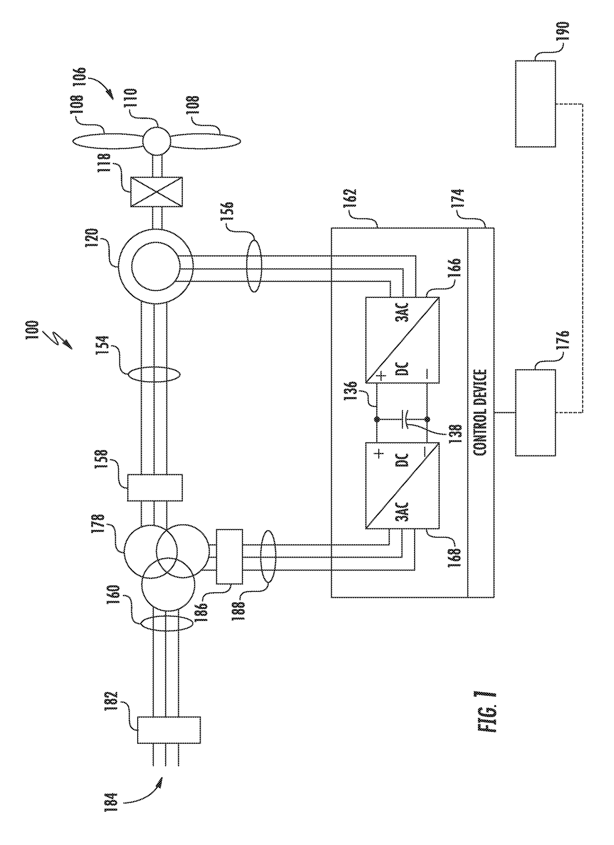
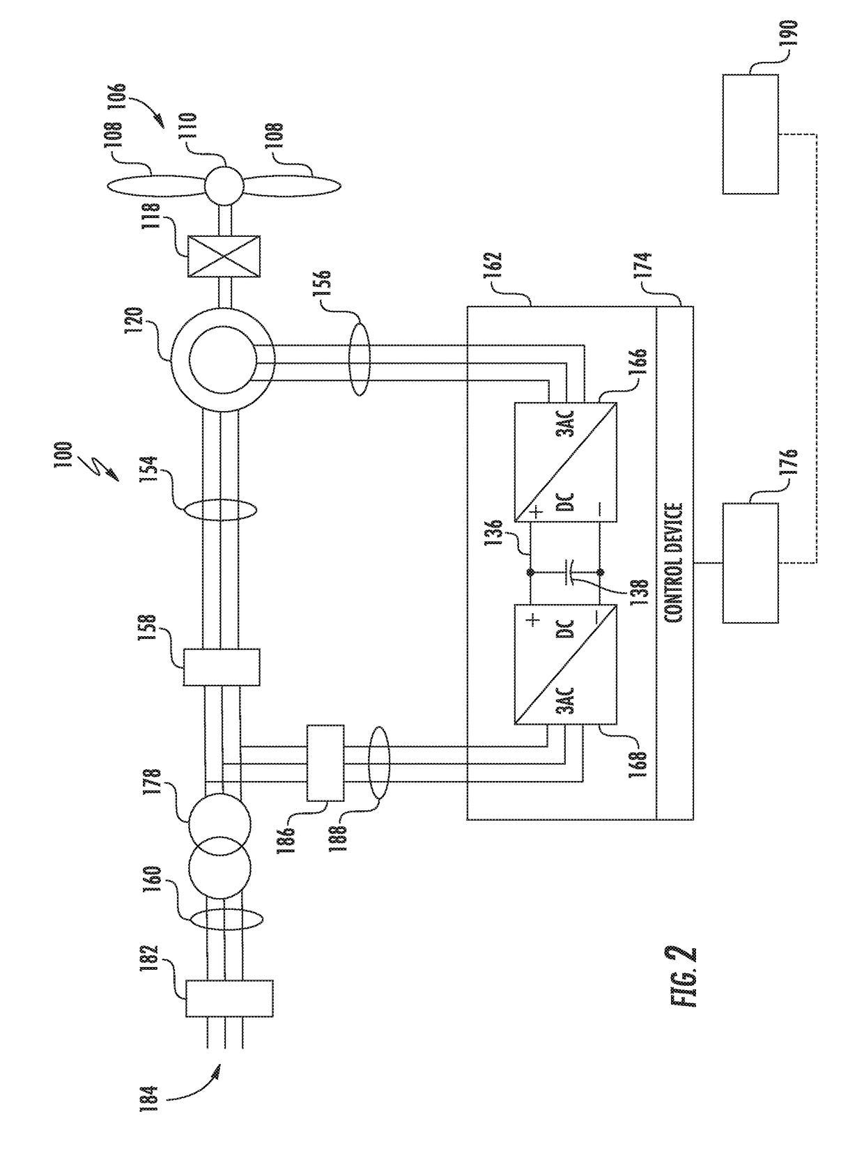
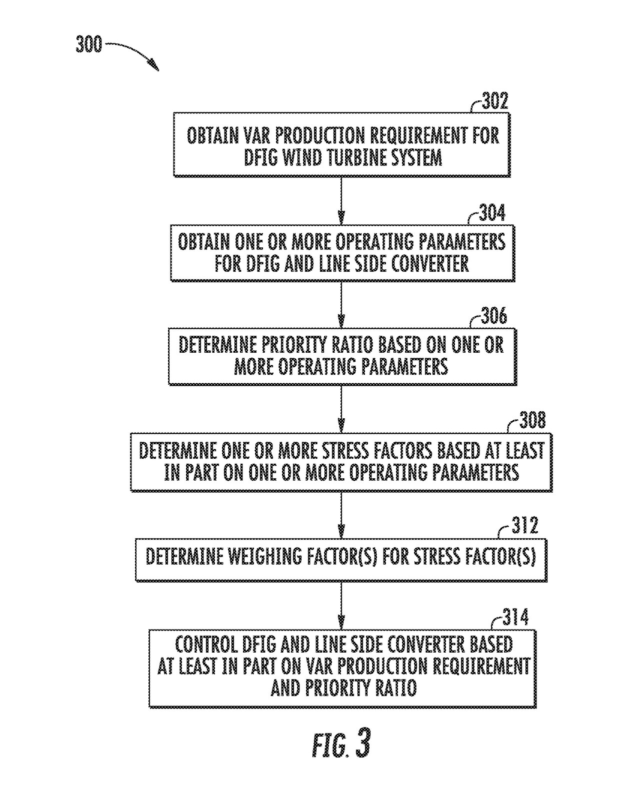
[0018]Generally, example aspects of the present disclosure are directed to systems and methods of allocating reactive power production in a DFIG wind turbine system. More particularly, a DFIG wind turbine system can include a DFIG with a rotor and a stator....


PUM


Abstract

Systems and methods for allocating reactive power production in a doubly-fed induction generator (DFIG) wind turbine system including a DFIG and a power converter including a line side converter and a rotor side converter are provided. A method can include obtaining a reactive power production requirement, obtaining one or more operating parameters for the DFIG and the line side converter, and determining a priority ratio based at least in part on the one or more operating parameters. The priority ratio can be a ratio of reactive power production between the DFIG and the line side converter. The method can further include controlling the DFIG and the line side converter based at least in part on the reactive power production requirement and the priority ratio such that the combined reactive power production from the DFIG and the line side converter meet the reactive power production requirement.

Description

FIELD[0001]The present disclosure relates generally to wind turbine power systems, and more particular to systems and methods for allocating reactive power production for a doubly-fed induction generator wind turbine system.BACKGROUND[0002]Wind turbine power systems, such as doubly-fed induction generator (DFIG) wind turbine systems, often include a power converter. For example, DFIG wind turbine systems can include a power converter with an AC-DC-AC topology, wherein a rotor side converter converts AC power from the rotor to DC power at a DC bus, and a line side converter converts the DC power from the DC bus to AC power suitable for an electrical grid. Thus, power generated by the DFIG can be provided to an electrical grid via two paths. For example, the stator of a DFIG can be synchronously connected to the electrical grid, while power generated by the rotor of the DFIG can be provided to the grid via the power converter.[0003]The DFIG can be configured to provide both real power...

Claims


Application Information

Patent Timeline
IPC IPC(8): H02P9/00
CPCH02P9/007H02P2101/15H02J2300/28H02J3/381Y02E10/76H02J3/388
Inventor WAGONER, ROBERT GREGORYHAQUE, TALHAHARDWICKE, JR., EDWARD WAYNEWILMER, DAVID SCOTT
Owner GENERAL ELECTRIC CO
Why Eureka
Try Eureka