
System and method for controlling a dual-fed induction generator in response to high-voltage grid events

a dual-fed induction generator and high-voltage grid technology, applied in the direction of generator control circuits, electric generator control, dynamo-electric converter control, etc., can solve the problems of high-voltage conditions on the grid and on the electrical systems of wind turbines, voltage on the entire high-voltage grid to increase, and the effect of reducing back to normal

Active Publication Date: 2014-03-06
GENERAL ELECTRIC CO
View PDF5 Cites 17 Cited by
  • Summary
  • Abstract
  • Description
  • Claims
  • Application Information

AI Technical Summary

Benefits of technology

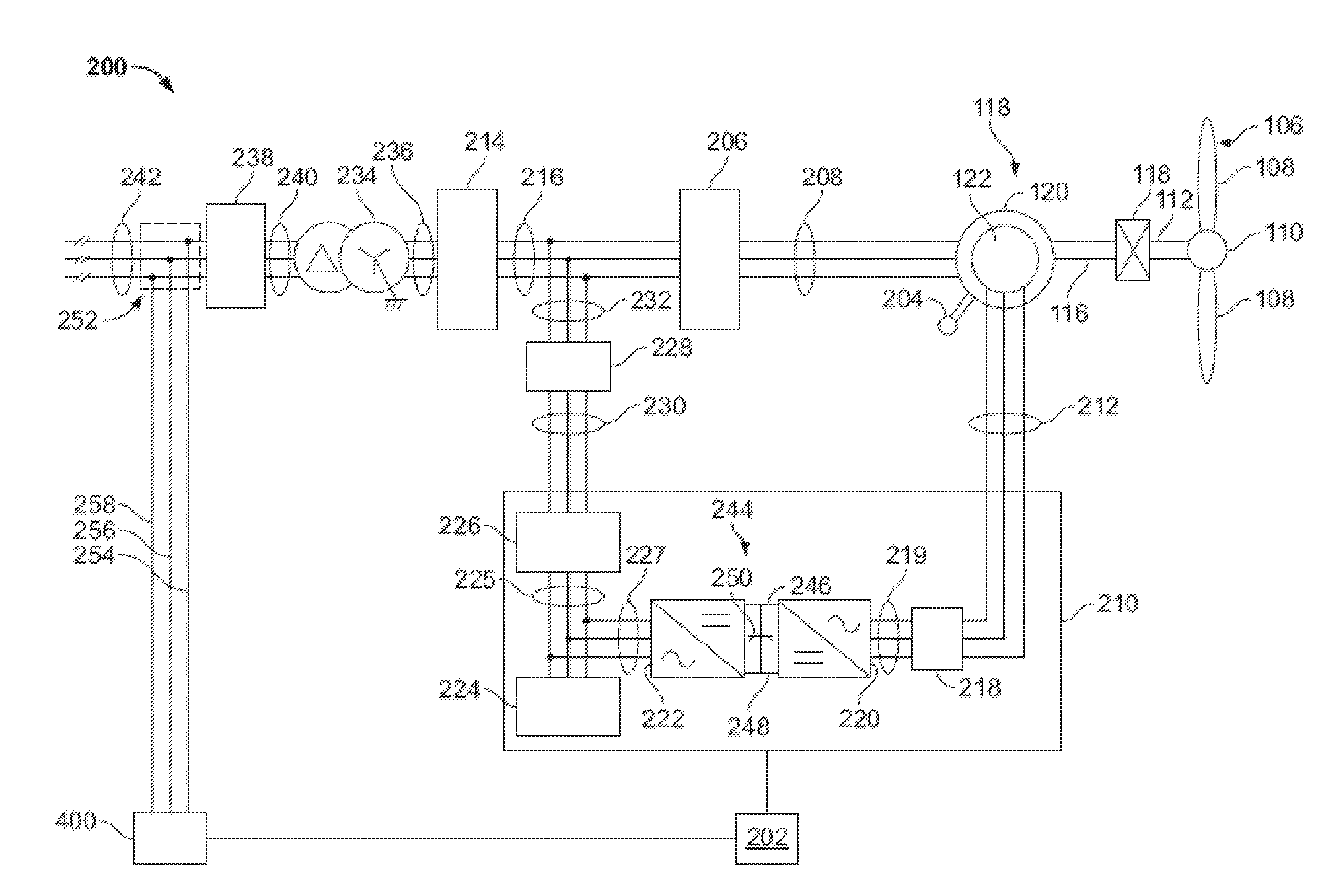
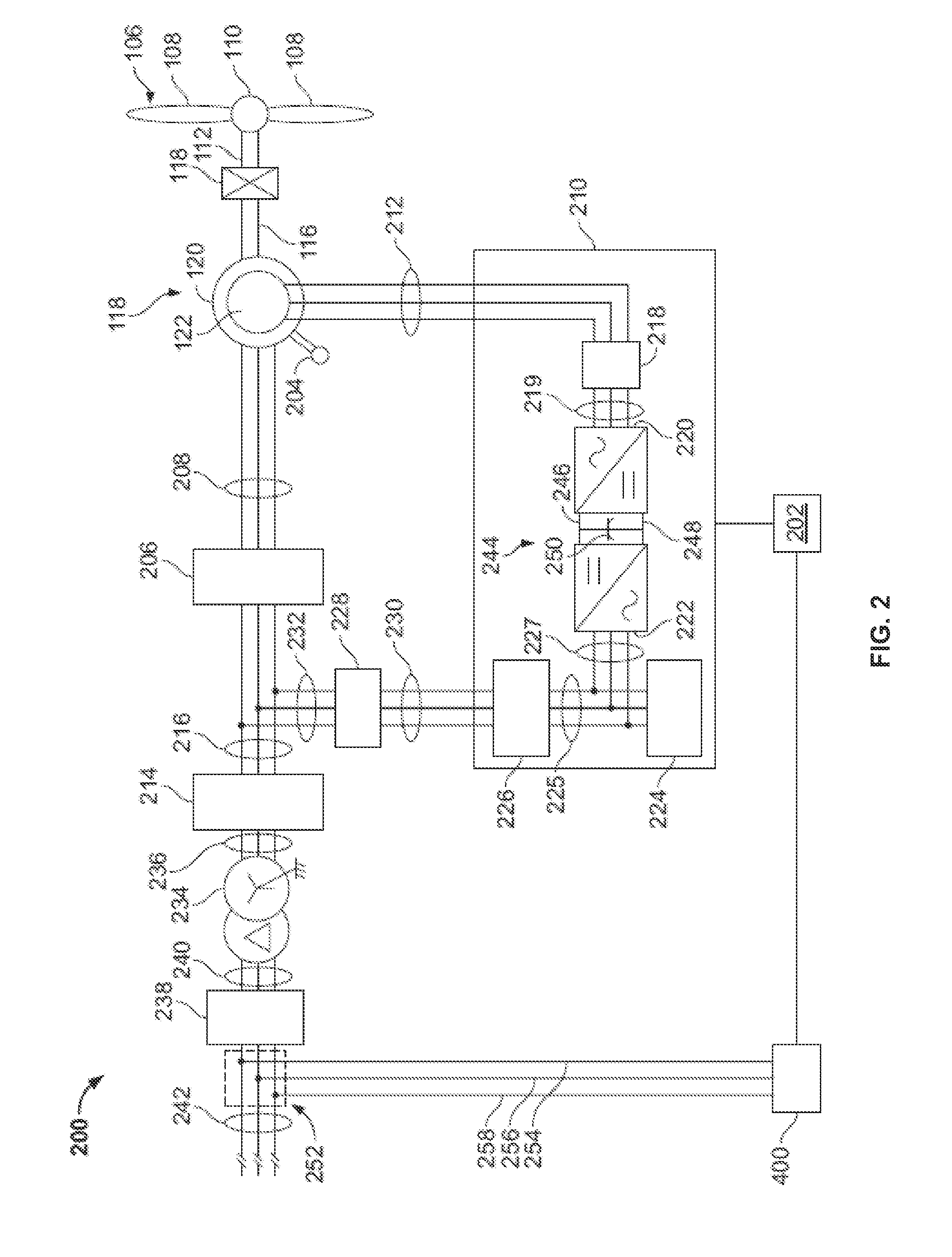
The patent describes a system for controlling a dual-fed induction generator (DFIG) in response to a high-voltage grid event. The system includes one or more DFIGs and a control system. The control system detects a grid fault and in response, regulates the output of the DFIG to protect it from damage. This is done by reducing the rotor torque producing current and lowering the internal voltage on the DFIG. The technical effects of this patent include reducing the risk of damage to the DFIG and ensuring a safe and reliable power generation system even during high-voltage grid events.

Problems solved by technology

The power grids can have many types of disturbances, some of which result in high-voltage conditions on the grid and on the wind turbine electrical systems.
These disturbances can include: (1) remote events that can cause the voltage on the entire high-voltage grid to increase well above normal with gradual reduction back to normal; (2) local grid faults that can cause voltage at the wind turbines to be depressed, followed by sudden removal of the faulted circuit element.
Each of the above-described events poses a potential for damage to the wind turbine electrical system due to high voltages within that system that exceed equipment capability.

Method used


Image

  • System and method for controlling a dual-fed induction generator in response to high-voltage grid events
  • System and method for controlling a dual-fed induction generator in response to high-voltage grid events
  • System and method for controlling a dual-fed induction generator in response to high-voltage grid events

Examples


Embodiment Construction

[0023]Before the present methods and systems are disclosed and described, it is to be understood that the methods and systems are not limited to specific synthetic methods, specific components, or to particular compositions. It is also to be understood that the terminology used herein is for describing particular embodiments only and is not intended to be limiting.

[0024]As used in the specification and the appended claims, the singular forms “a,”“an” and “the” include plural referents unless the context clearly dictates otherwise. Ranges may be expressed herein as from “about” one particular value, and / or to “about” another particular value. When such a range is expressed, another embodiment includes from the one particular value and / or to the other particular value. Similarly, when values are expressed as approximations, by use of the antecedent “about,” it will be understood that the particular value forms another embodiment. It will be further understood that the endpoints of eac...


PUM


Abstract

In one aspect, a method for controlling a dual-fed induction generator (DFIG) during a high-voltage grid event is provided. The method includes setting, by a controller, an output of a closed-loop portion of a rotor current regulator to a fixed value such that a predictive feed-forward path sets an internal voltage for the DFIG; and detecting, by the controller, a condition of high dc voltage on a dc link or a condition predictive of high dc voltage on the dc link, and in response reduce a rotor torque producing current command to approximately zero, wherein the dc link connects a line-side converter connected to a system bus and a rotor-side converter connected to a rotor of the DFIG.

Description

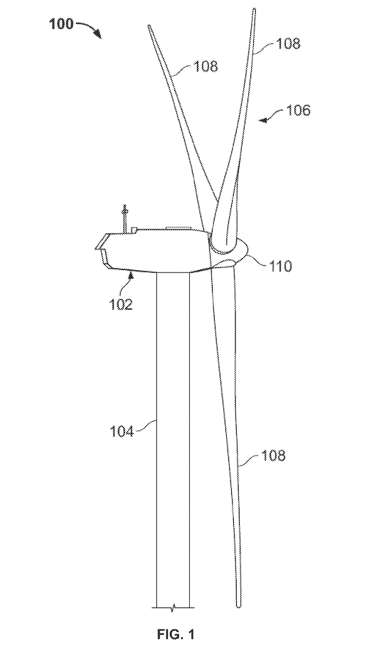
FIELD OF THE INVENTION[0001]The present subject matter relates generally to electrical machines and, more particularly, to a system and method for controlling a dual-fed induction generator (DFIG) in response to high-voltage grid events.BACKGROUND OF THE INVENTION[0002]Generally, a wind turbine generator includes a turbine that has a rotor that includes a rotatable hub assembly having multiple blades. The blades transform mechanical wind energy into a mechanical rotational torque that drives one or more generators via the rotor. The generators are generally, but not always, rotationally coupled to the rotor through a gearbox. The gearbox steps up the inherently low rotational speed of the rotor for the generator to efficiently convert the rotational mechanical energy to electrical energy, which is fed into a utility grid via at least one electrical connection. Gearless direct drive wind turbine generators also exist. The rotor, generator, gearbox and other components are typically m...

Claims


Application Information

Patent Timeline
Patent Type & Authority Applications(United States)
IPC IPC(8): H02P9/10
CPCH02P9/007H02P9/10H02J2300/28H02J3/381H02J3/48H02J3/50Y02E10/76
Inventor LARSEN, EINAR VAUGHNKLODOWSKI, ANTHONY MICHAELBARKER, SIDNEY ALLEN
Owner GENERAL ELECTRIC CO
Learn More