
Jewelry Illumination System

a technology for lighting systems and jewelry, applied in the field of illumination systems for jewelry, can solve the problems that the jewelry industry has not evolved much, and the use of technology has not evolved much

Pending Publication Date: 2019-01-17
FINN BRUCE LEON
View PDF20 Cites 2 Cited by
  • Summary
  • Abstract
  • Description
  • Claims
  • Application Information

AI Technical Summary

Benefits of technology

This patent describes a new jewelry illumination system that uses micro control systems and tiny LEDs to produce a front-light illumination for diamonds and other faceted stones, resulting in increased fire, brilliance, and scintillation. The system can be incorporated into jewelry pieces and can also illuminate the adjacent skin of the wearer. The color and quality of the light can be designed to enhance the appearance of the jewelry and the wearer's eyes. The system uses a light source that is self-illuminating, making it ideal for wearing at night or when attending social events.

Problems solved by technology

It is desirable to produce the most fire, brilliance and scintillation as possible from many pieces of jewelry however there has not been a jewelry illumination system to date that “front” lights or “scrapes” faceted stones such as diamonds or crystals with light designed to optimally achieve these results.
Although there have been major advances in LED lighting technology and the architectural, photographic, automotive and theatrical lighting industries have all shown tremendous use of new technologies the jewelry industry has not evolved into use of the technology including changeable tiny, bright light sources and color control including RGB color changing.
Illuminated jewelry which began with glow sticks turned into necklaces, inexpensive plastic blinky adornments and backlit crystal earrings and such have not evolved much over decades despite significant improvements in portable tiny lighting technology nor has illumination evolved in the jewelry world to fine jewelry.

Method used


Image

  • Jewelry Illumination System
  • Jewelry Illumination System
  • Jewelry Illumination System

Examples


Embodiment Construction

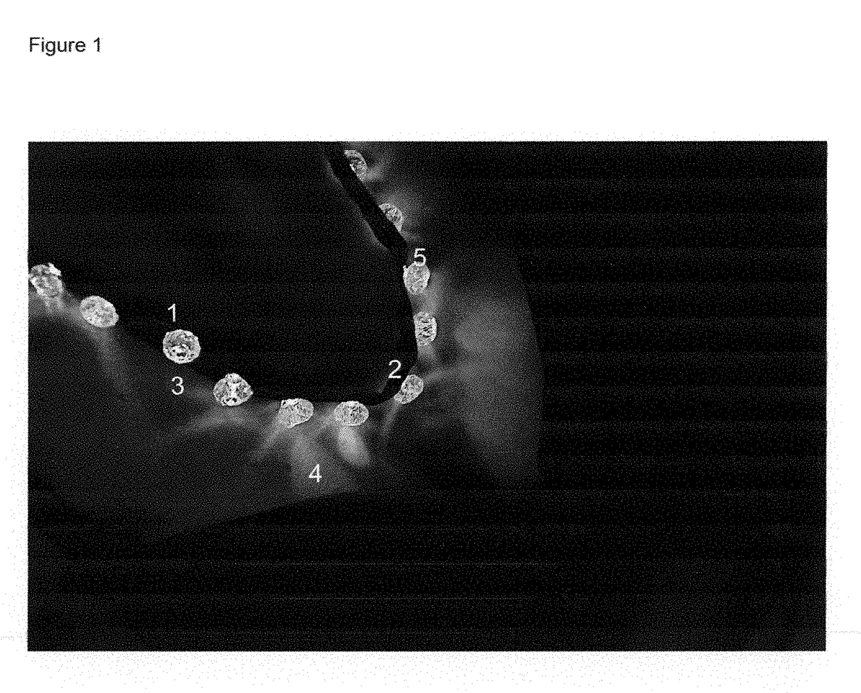
[0040]Referring now to the drawings the invention is shown in FIG. 1 generally at numeral 1 large hole crystal beads are used to house the LEDs 2 mounted to directionally project through the aperture of the bead 3 (housing) onto the adjacent skin 4 and illuminate the translucent material of said bead(s) 5

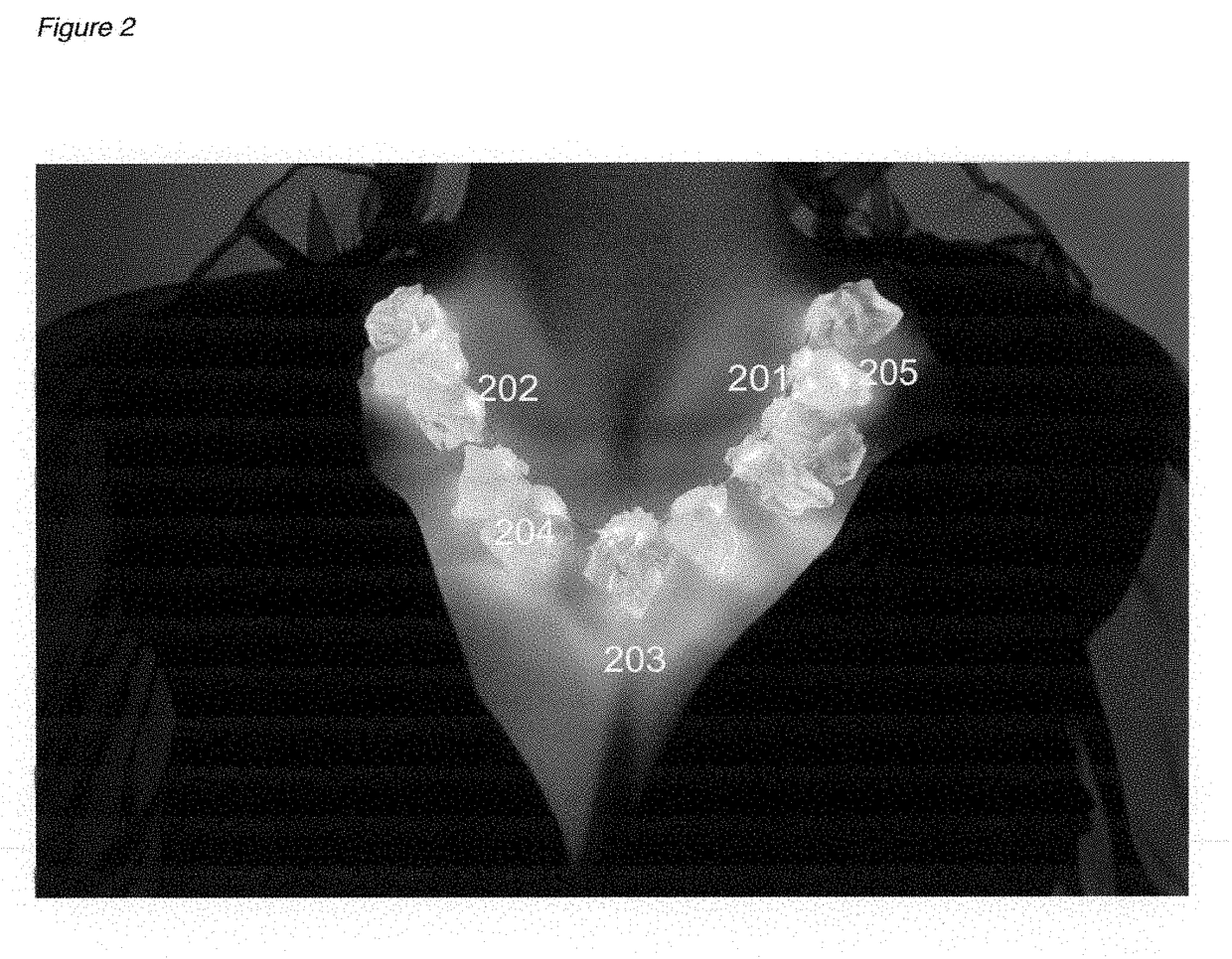
[0041]As shown in FIG. 2. a flexible fabric LED light ribbon 201 is utilized with powerful, directional LED's 202 that can transmit appreciable viewable light to the adjacent skin of the wearer 203 when projected through a translucent material such as silicone cubes / chunks 204 (as shown). Although the light projected into the translucent material scatters and is absorbed to some degree this “glow” of the “backlit” material can be additionally attractive 205. The color of said light can be chosen to complement the skin tone of the wearer. In this example a warm white light is used to “glow” the adjacent skin of the wearer 203.

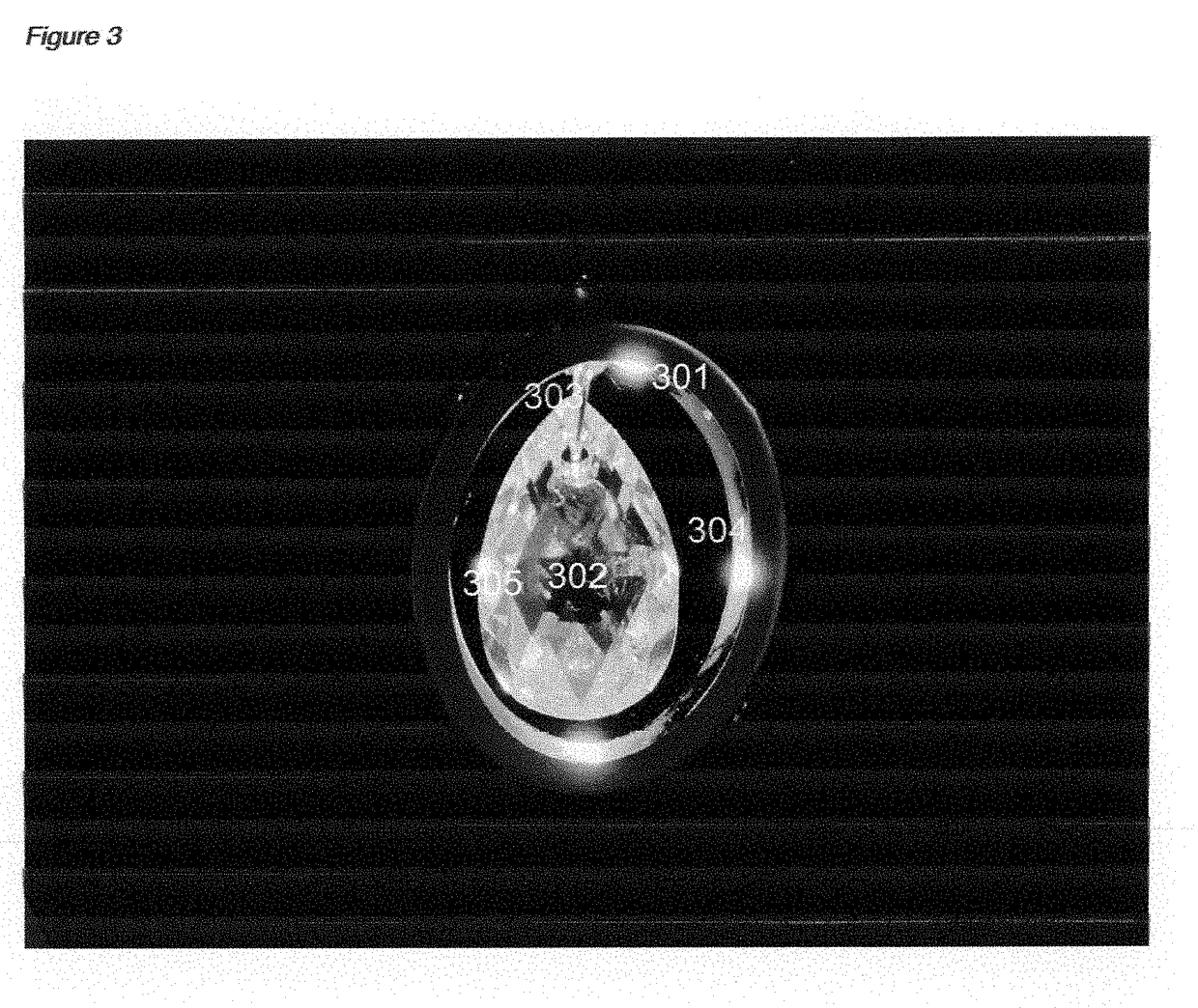
[0042]FIG. 3 shows the preferred “picture frame” embodimen...


PUM


Abstract

Illuminated jewelry wearable as earrings, body rings, necklaces or the like includes a single or multiple light source(s) that cast, scrape, front light and otherwise illuminate the jewelry desired either incorporated there in or adjacently. Additional desirous effects may include body / skin illumination directly, indirectly, reflected or refracted. Light source(s) can include LED(s), chemo luminescence, incandescent, electro luminescent or other.

Description

BACKGROUND OF THE INVENTIONScope of Invention[0001]This invention relates generally to illuminated jewelry and more particularly to LED or other type of jewelry that illuminates (casts light) on portions of itself and / or adjacent jewelry or the skin of the wearer.Related Art[0002]It is well known to utilize illuminated jewelry for backlit translucent crystal earrings, inexpensive bracelets, necklaces and rings, illuminated translucent medallions and other costume jewelry applications.[0003]U.S. Pat. No. 5,504,664 of Ostema shows a tiny battery housing and stem that connects to a conductive rubber material and back lights a plastic crystal.[0004]This popular product certainly has it's place and market.[0005]These types of costume jewelry are not designed to illuminate the front or reflective facets of jewelry pieces such as crystals and diamonds, adjacent jewelry or the skin of the wearer.[0006]U.S. Pat. No. 5,951,158 describes a single source earring housing with fiber optic “tentac...

Claims


Application Information

Patent Timeline
IPC IPC(8): A44C15/00A44C25/00A44C7/00F21V23/02F21S4/24F21V23/00F21V3/00
CPCA44C15/0015A44C15/005A44C15/0005A44C25/001A44C15/0045F21Y2115/10F21V23/02F21S4/24F21V23/003F21V3/00A44C7/00
Inventor FINN, BRUCE LEON
Owner FINN BRUCE LEON
Learn More