

Inkjet head maintenance device and inkjet head maintenance method
a maintenance device and inkjet head technology, applied in printing and other directions, can solve the problems of inability to coat the inkjet head, inability to clean the inkjet head, and trapped cleaning liquid in the grooves, so as to improve the cleaning of the inkjet head and remove dirt reliably.
- Summary
- Abstract
- Description
- Claims
- Application Information
AI Technical Summary
Benefits of technology
Problems solved by technology
Method used
Image

Examples
first embodiment
Effect of First Embodiment
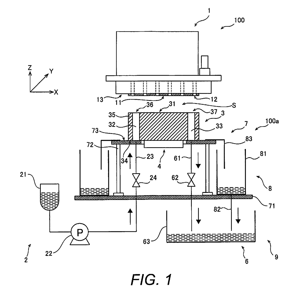
[0048]The inkjet head maintenance device 100a according to the first embodiment described above comprises the base 3 that has the upper face 31 disposed closely opposite the nozzle face 11 of the inkjet head 1 to form the liquid reservoir space S during maintenance of the inkjet head, and includes the liquid supply hole 32 and the liquid collection hole 33 that open to the upper face; the liquid supply component 2 that supplies liquid from the liquid supply hole 32 to the liquid reservoir space S; and the liquid collection component 6 that collects the liquid in the liquid reservoir space S from the liquid collection hole 33. The maintenance device 100a having this basic configuration and the maintenance method that makes use of this device afford the following effects.
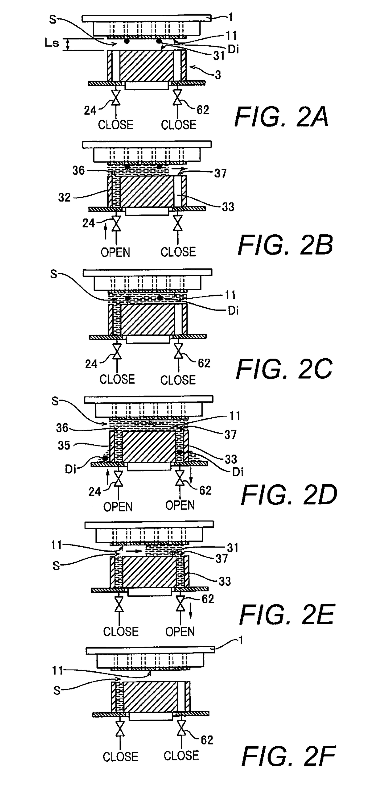
[0049]When the maintenance device 100a is used to perform when cleaning, which is a type of maintenance, first cleaning liquid is supplied from the supply hole 32 of the base 3 into the liqui...
second embodiment
Action and Effect of Second Embodiment
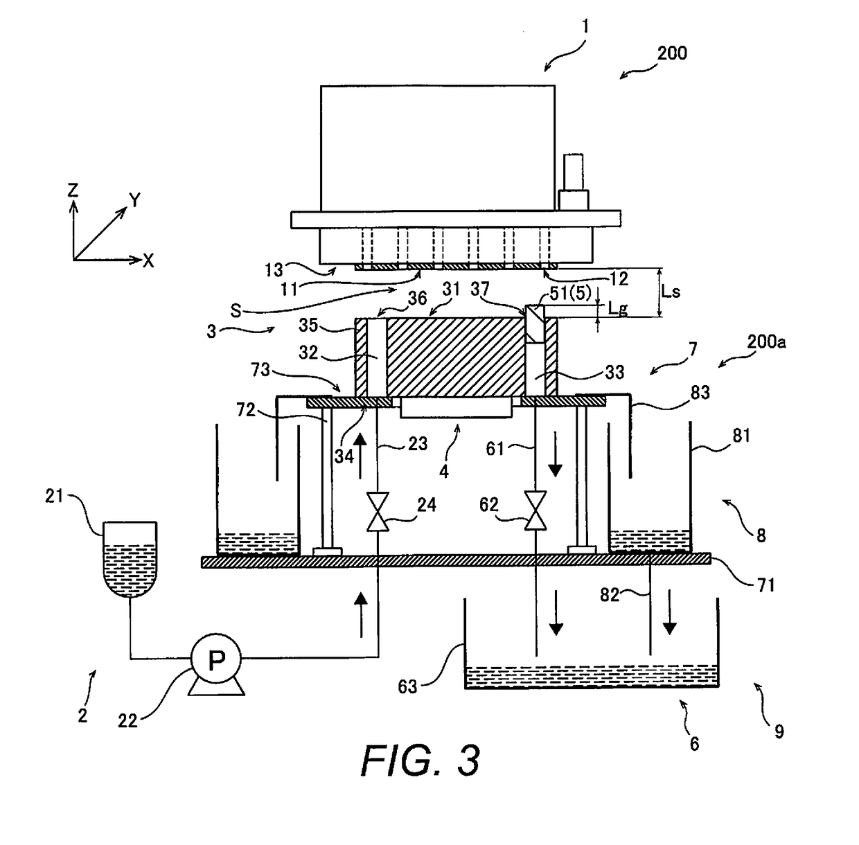
[0056]With the maintenance device 200a according to the second embodiment, the base 3 is configured to include the liquid collection promotion means 5 for accelerating the collection of liquid. More specifically, the collection attracting member 51, which is the liquid collection promotion means 5, is added to the opening 37 of the liquid collection hole 33 of the base 3. The collection attracting member 51 is plate-shaped, and comprises the upper portion 53, which is a first portion on the outside of the liquid collection hole 33, and the lower portion 54, which is a second portion on the inside of the liquid collection hole 33, and the upper portion 53 has a shape that is contiguous with the lower portion 54. Consequently, the liquid outside the liquid collection hole 33 flows down along the upper portion 53 and the lower portion 54 and is collected inside the liquid collection hole 33, which generates a force that draws the liquid at the uppe...
modification examples
[0074]The embodiments disclosed herein are examples in all respects and are not limiting in nature. The scope of the present invention is indicated not by the description of embodiments, but by the scope of the claims. Furthermore, all changes (modification examples) within the meaning and range of equivalency of the claims are included.
[0075]In the first and second embodiments, an example is given in which the liquid supply hole 32 and the liquid collection hole 33 are provided near the end that is directly opposite the base 3 in the X direction, but the present invention is not limited to this. For example, one of them may be provided near the center of the base 3. Furthermore, they may be arranged close to each other, and they may be disposed anywhere, such as at the end, the center part, or the like of the base 3. It is also possible to form one hole that serves as both the liquid supply hole 32 and the liquid collection hole 33.
[0076]Furthermore, in the first and second embodim...
PUM
 Abstract
Description
Claims
Application Information