Delayed fin deployment wiper plug

a technology of wiper plugs and delayed fins, which is applied in the direction of sealing/packing, earthwork drilling and mining, and well accessories, etc., can solve problems such as event failure, and achieve the effect of preventing contamination

Active Publication Date: 2019-01-17
CONOCOPHILLIPS CO
View PDF8 Cites 6 Cited by
  • Summary
  • Abstract
  • Description
  • Claims
  • Application Information

AI Technical Summary

Benefits of technology

[0011]During cementing operations, a wiper plug is typically used to act as a solid barrier between different fluid types to prevent contamination between them. Because the wiper plug material is in contact with the inner diameter of the tubular, the fins experience wear leading to eventual failure. The solution described herein allows for fresh fins to be deployed on a given wiper plug, even while downhole, and contact the tubular inner diameter at some time after the plug has been deployed.
[0012]The tool utilizes a blocking sleeve and atmospheric chamber to protect one or more wiping fins from wear until a time when wear is apparent, and the sleeve shifts, thus exposing new fins for use. These new “fresh” fins allow for better cleaning as opposed to the ones that have been undergoing wear through the previous length of tubular.
[0014]The blocking sleeve is attached to some type of piston with an atmospheric chamber on one side. The piston is held in place with shear screws or any other removable element. When the plug reaches a point that the hydrostatic pressure exerts a force great enough to shear the screws the piston moves shifting the blocking sleeve and exposing the second set of fins. The number and type of shear screws can be adjusted allowing the depth at which it activates to be customized for each application. The second set of fins compensates for any wear on the original set and increases the overall wiping efficiency of the plug system.
[0015]If desired, the shear mechanism can be repeated for multiple sets of fins, housed inside the same, albeit longer, sleeve. Different shear strength retaining pins can be activated at different pressures, thus allowing sequential deployment of additional fins.
[0017]This solution allows for new fresh fins to be engaged against the casing, e.g., just before the plug enters the curve / lateral of a well. These fresh fins have not experienced any type of wear, having been protected by the outer sleeve. Once deployed, they will be fresh and have much better wiping efficiency, thus reducing the risk of cement or other debris being left behind.
[0018]A wiper plug with a second or more deployable fins sets could be used in any wellbore cementing operation where debris left in the casing would be detrimental to future operations. In the case of horizontal wells with toe initiator valves, the debris left by conventional wiper plugs can clog the tool and render it useless. This invention would further reduce the debris or eliminate it completely, allowing for a higher rate of success.

Problems solved by technology

Because the wiper plug material is in contact with the inner diameter of the tubular, the fins experience wear leading to eventual failure.

Method used


Image

  • Delayed fin deployment wiper plug
  • Delayed fin deployment wiper plug
  • Delayed fin deployment wiper plug

Examples


Embodiment Construction

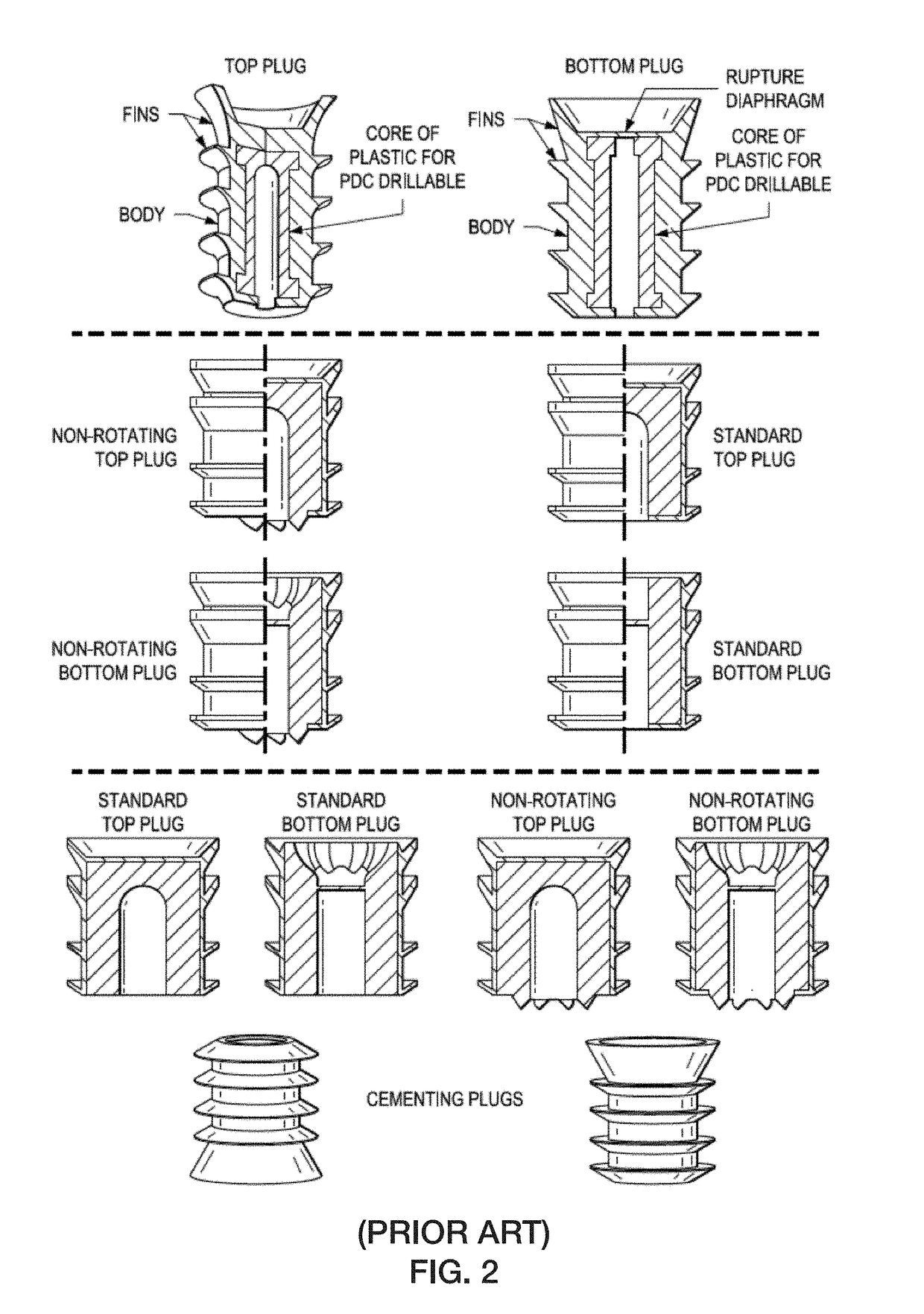
[0038]The disclosure provides novel wiper plugs with a second (or more) set(s) of wiper fins that are deployable on command. Generally speaking, the wiper plug has a piston that can be activated to raise a sleeve, under which are housed one or more additional fin sets. When the piston is activated, it lifts, raising the sleeve and exposing the fins that were previously hidden inside the sleeve.

[0039]The piston can be activated in any suitable manner, and one common means would be to allow changing pressure to raise the sleeve, e.g., by shearing shear pins, screws, bolts and the like, or by overcoming the holding pressure of a spring clip, or other equivalent device. Other activation methods include timer activated, airbag activated, dissolvable retainer, deterioration of a retaining ring, deterioration of retaining wiper fins, and the like.

[0040]The invention includes any one or more of the following embodiment(s), in any combination(s) thereof:

[0041]In at least one embodiment, a de...


PUM


Abstract

A delayed fin deployment wiper plug has a tubular body, which has a closed top and a piston therein. The piston is supported at one or more locations inside the tubular body by one or more sets of shear pins or spring clips or some equivalent device. The piston is connected to or abutted to a sleeve that covers an upper portion of the tubular body, containing therein one or more sets of deployable fins that are not exposed for use unless the piston is activated and raises the sleeve.

Description

PRIOR RELATED APPLICATIONS[0001]This application claims priority to U.S. Provisional Application No. 62 / 532,762, filed Jul. 14, 2017, the disclosure of which is expressly incorporated herein by reference in its entirety for all purposes.FIELD OF THE DISCLOSURE[0002]The disclosure generally relates to devices for use in downhole cementing operations, their design, manufacture, deployment, and use.BACKGROUND OF THE DISCLOSURE[0003]Before any well drilling is initiated, engineers create a well plan and architectural diagram, showing the hole and casing sizes needed to drill the well to its desired depth. A typical wellbore architectural diagram for an onshore well is shown in FIG. 1. Normal drilling operations include drilling the hole and adding new joints of pipe, one at a time, as the hole deepens. It also involves “tripping” the drill string all the way out of the hole to put on a new bit and then running it back to the bottom (making a round trip). Other key steps include running ...

Claims


Application Information

Patent Timeline
Patent Type & Authority Applications(United States)
IPC IPC(8): E21B33/16E21B37/04
CPCE21B37/04E21B33/16E21B33/165E21B37/00E21B37/045E21B33/14
Inventor NANNEY, JAMES G.WHITE, MATTHEW L.
Owner CONOCOPHILLIPS CO
Why Eureka
Try Eureka