
Design for a tessellated magnetic stage for the parallel assembly of diamagnetic components

Inactive Publication Date: 2019-01-17
SELFARRAY INC
View PDF0 Cites 1 Cited by
  • Summary
  • Abstract
  • Description
  • Claims
  • Application Information

AI Technical Summary

Benefits of technology

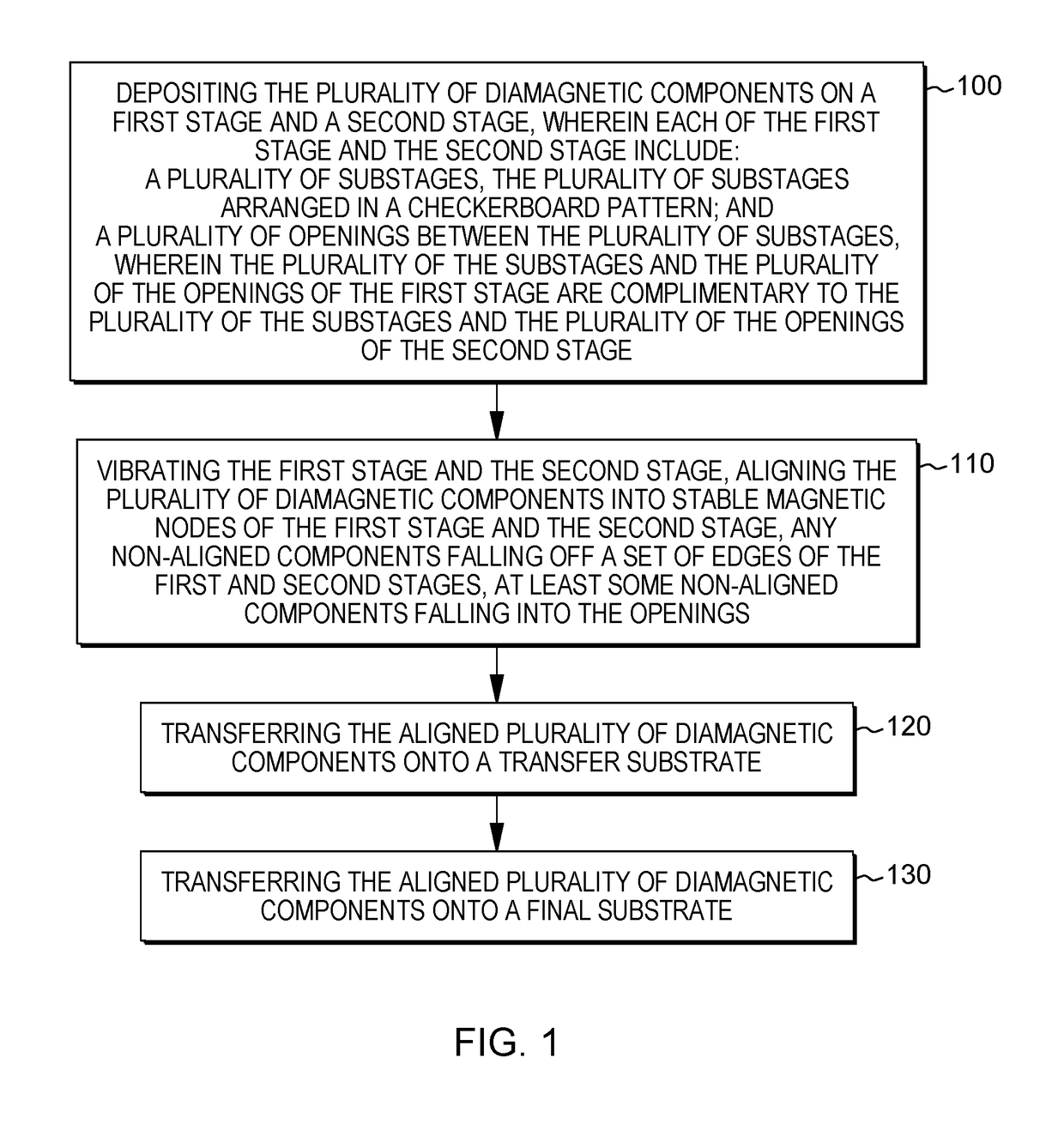
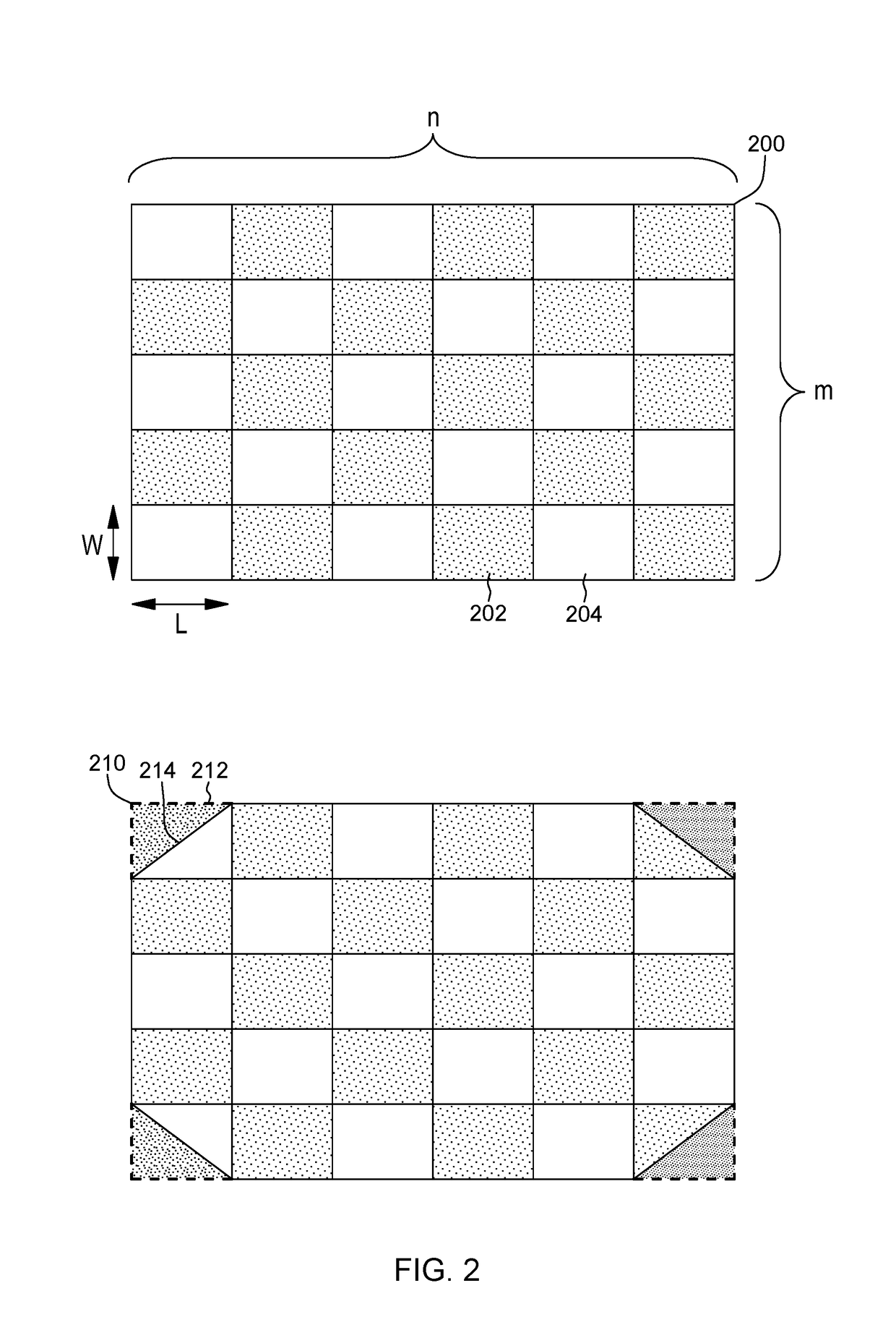
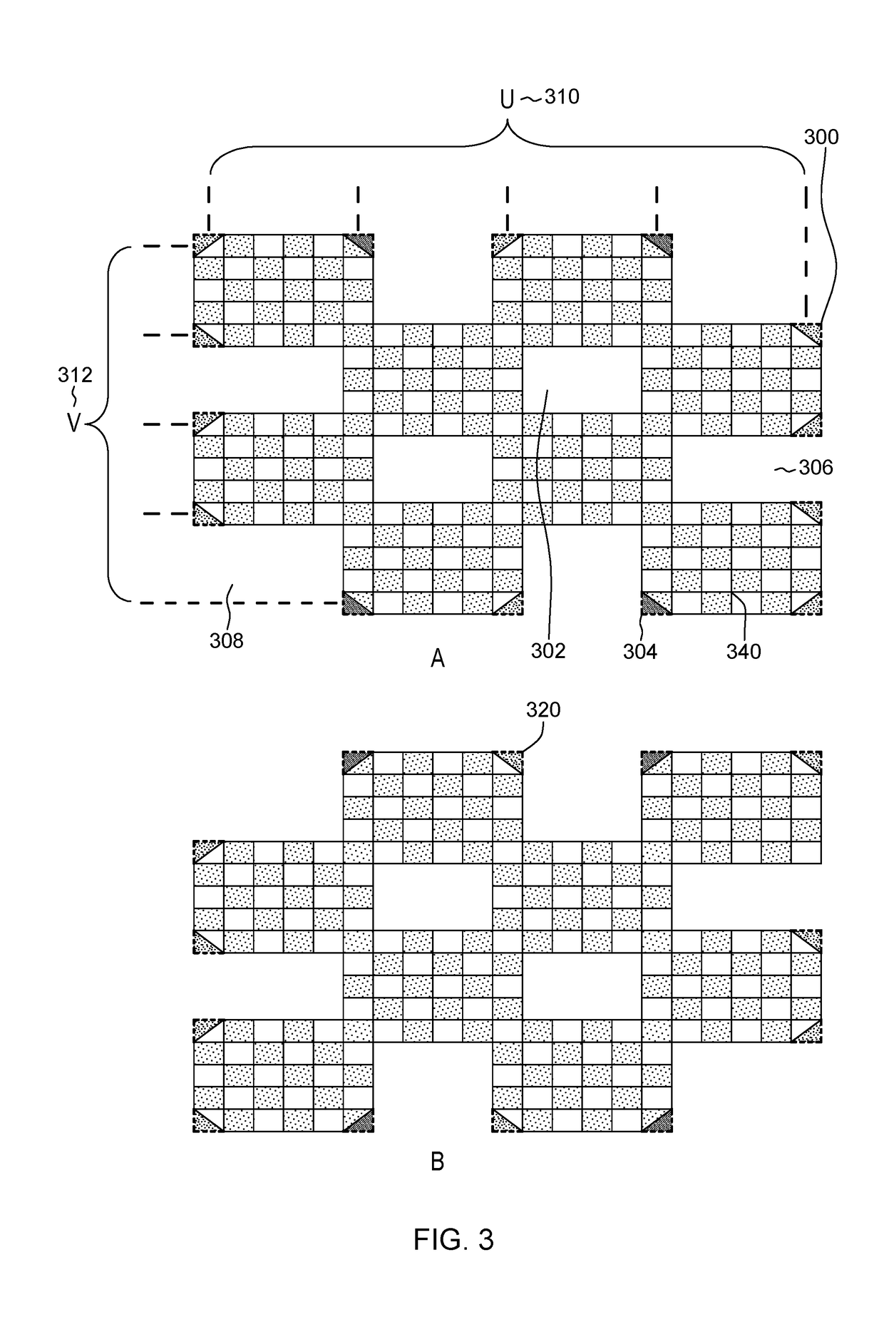
The patent describes a system and method for assembling multiple magnetic components. The system includes first and second stages with substages arranged in a checkerboard pattern and openings between them. The components are deposited on the stages, and then vibrated to align them. Non-aligned components fall off the edges of the stages or into the openings. The aligned components are then transferred onto a substrate. The technical effect of this system is that it allows for precise placement of magnetic components in a compact design.

Problems solved by technology

Current methods of assembling components, such as light emitting diodes (LEDs), can be slow and unable to manipulate very small components.
The assembly time, yield, and associated machine costs can determine the overall production volume and cost of a display made using these techniques.

Method used


Image

  • Design for a tessellated magnetic stage for the parallel assembly of diamagnetic components
  • Design for a tessellated magnetic stage for the parallel assembly of diamagnetic components
  • Design for a tessellated magnetic stage for the parallel assembly of diamagnetic components

Examples


Embodiment Construction

[0026]Aspects of the present invention and certain features, advantages, and details thereof, are explained more fully below with reference to the non-limiting embodiments illustrated in the accompanying drawings. Descriptions of well-known materials, fabrication tools, processing techniques, etc., are omitted so as to not unnecessarily obscure the invention in detail. It should be understood, however, that the detailed description and the specific examples, while indicating embodiments of the invention, are given by way of illustration only, and are not by way of limitation. Various substitutions, modifications, additions and / or arrangements within the spirit and / or scope of the underlying inventive concepts will be apparent to those skilled in the art from this disclosure. Note also that reference is made below to the drawings, which are not drawn to scale for ease of understanding, wherein the same reference numbers used throughout different figures designate the same or similar ...


PUM


Abstract

Systems, and methods of use thereof, for assembling a plurality of diamagnetic components. The system including a first stage and a second stage, wherein each of the first stage and the second stage include a plurality of substages, the plurality of substages arranged in a checkerboard pattern, and a plurality of openings between the plurality of substages, wherein the plurality of the substages and the plurality of the openings of the first stage are complimentary to the plurality of the substages and the plurality of the openings of the second stage.

Description

CROSS-REFERENCE TO RELATED APPLICATION[0001]This application claims priority benefit under 35 U.S.C. § 119(e) to U.S. Provisional Application No. 62 / 531,493, filed 12 Jul. 2017, and entitled DESIGN FOR A TESSELATED MAGNETIC STAGE FOR THE PARALLEL ASSEMBLY, OF DIAMAGNETIC COMPONENTS, the entirety of which is incorporated herein by reference in its entirety.FIELD OF THE INVENTION[0002]The present invention relates to a set of tessellated magnetic stages for directed self-assembly of components into a grid array and more particularly, for parallel assembly of light emitting diode (LED) dies into a grid array.BACKGROUND[0003]Current methods of assembling components, such as light emitting diodes (LEDs), can be slow and unable to manipulate very small components. For larger scale displays, assembly time of LED components increases quadratically as pixel pitch decreases. The assembly time, yield, and associated machine costs can determine the overall production volume and cost of a displa...

Claims


Application Information

Patent Timeline
IPC IPC(8): H01L21/683H01L25/075H01L33/62B65G47/92
CPCH01L21/6835H01L25/0753H01L33/62H01L2221/68363H01L2933/0066H01L2221/68309B65G47/92H01L2221/68354
Inventor DURNIAK, MARK
Owner SELFARRAY INC
Learn More