
Plasma torch system

a plasma torch and torch technology, applied in plasma welding apparatus, plasma technique, manufacturing tools, etc., can solve the problems of high material use of titanium metal, large lead time in metal object fabrication, and typically reduced material quality, so as to improve the throughput and yield of products, without the risk of overheating, and the effect of stable and repeatable plasma transfer arc characteristics

Active Publication Date: 2021-09-28
NORSK TITANIUM
View PDF14 Cites 2 Cited by
  • Summary
  • Abstract
  • Description
  • Claims
  • Application Information

AI Technical Summary

Benefits of technology

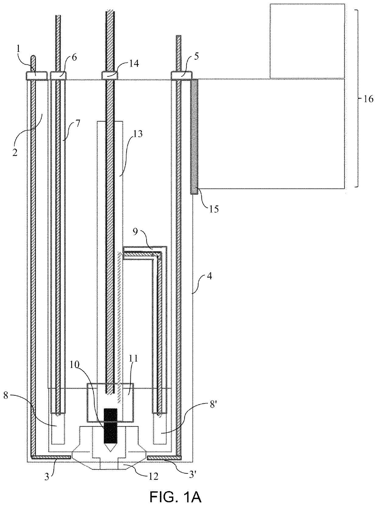
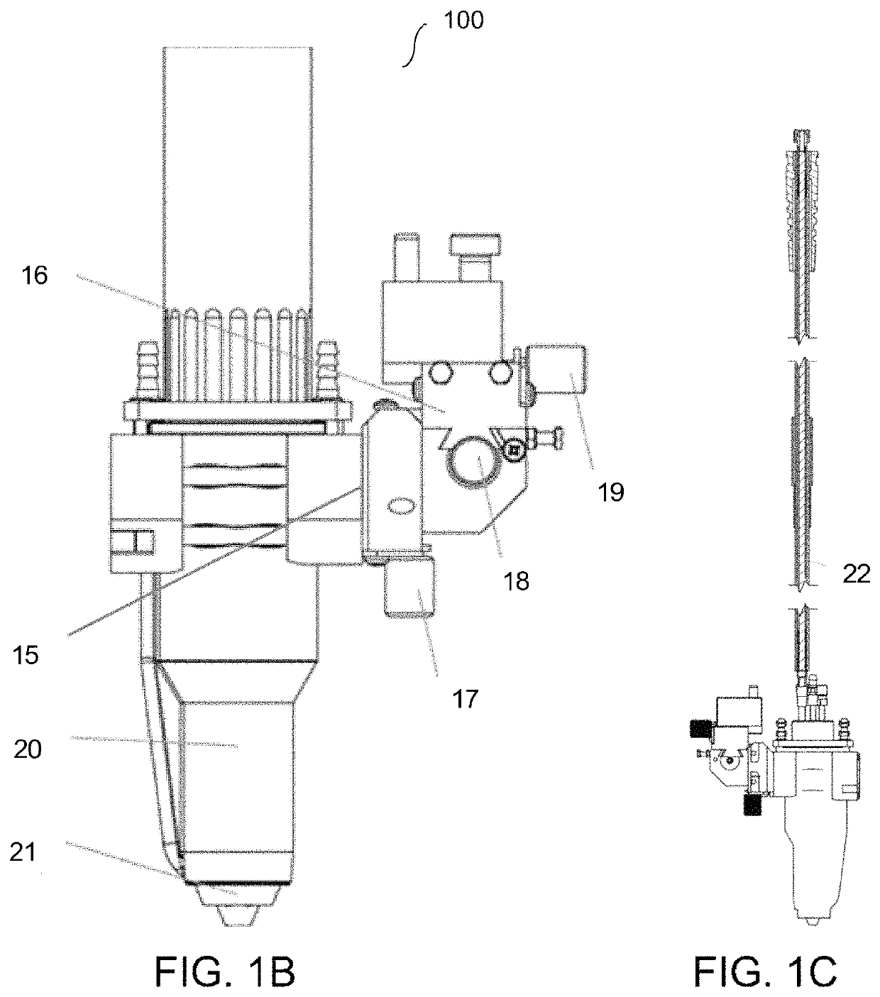
[0010]An objective of the present invention is to provide a fluid-cooled melting tool that allows increased throughput and yield of products produced using additive manufacturing without the risk of overheating. Another objective is to provide a fluid-cooled melting tool for use in additive manufacturing processes that can utilize high electric current. Provided herein are fluid-cooled melting tools that include a dual circuit cooling design. The fluid-cooled melting tools provided herein can handle electric current of 400 amps or more. The fluid-cooled melting tools provided herein exhibit stable and repeatable plasma transferred arc (PTA) characteristics over a wide range of current, including current of 400 amps or more, whether pulsed or non-pulsed, and over varying plasma gas flow inputs. The fluid-cooled melting tools provided herein have a slim design that allows multiple melting tools to be used in combination, such as in a two torch or multi-torch system. The fluid-cooled melting tools have a current capacity of 400 amps or more at 100% duty cycle and produce a stable arc at high current. Because of the arrangement of the cooling circuits, the fluid-cooled melting tools provided herein allow for change of consumables without loss of cooling fluid.
[0015]This invention also addresses the need for an improved melting tool that can reliably handle electric current of 400 amps or more without overheating. This invention further addresses the need for a method of increasing throughput and yield of objects produced via additive manufacturing, where the parts exhibit smooth, well-defined deposition boundaries.
[0016]The fluid-cooled melting tools provided herein can be PTA torches, and can increase the deposition rate of metallic material during an additive manufacturing process by supplying the consumable electrode in the form of a wire, using a relatively high flow rate of electric charge in the electrode of the torch, and cooling the melting tool with the dual circuit fluid cooling system. The fluid cooling system incorporates cooling channels into the melting tool. The cooling channels can be positioned close to where the heat is being generated in order to remove thermal energy from the melting tool. In some embodiments, the cooling channels are located in sufficient proximity to the electrode or nozzle or jacket or any combination thereof to allow rapid transfer of thermal energy to the cooling channels and out of the melting tool to prevent overheating of the melting tool. The melting tools provided herein include a dual channel cooling design, where one channel cools the electrode and / or nozzle, and another channel cools the jacket of the melting tool.
[0021]The fluid-cooled melting tools provided herein containing a dual circuit cooling design can be configured to have a slim design. The slim design means that melting tool requires very little space and is therefore much easier to install, especially if more than one melting tool is used in the system, such as in a two torch additive manufacturing system. The dual circuit cooling design produces a stable arc over a wide current working range, such as from about 10 A to about 400 A. Because of the configuration of the dual circuit cooling design in relation to the arrangement of the consumables (e.g., the electrode or nozzle), the consumables readily can be changed without loss of cooling fluid from the cooling circuits.

Problems solved by technology

These techniques have a number of disadvantages, such as high material use of the expensive titanium metal and large lead times in the fabrication of the metal object.
Casting, which often can be used for production of a potentially near-net-shape object, typically has a reduced material quality due to lack of control of solidification and cooling rates.
Tooling costs and the inability to prepare objects with complex shapes are additional disadvantages of the conventional methods.
The accuracy of the welding technique is usually too coarse to allow directly forming the object with acceptable dimensions.
A problem to be addressed is the speed of deposition of material on the base material to form the workpiece.
Use of high current, however, can produce a number of problems.
If the change in current is not controlled, a rapid overheating of the electrode can occur, which can potentially damage the workpiece of the equipment itself.
The problems that can result from use of high currents can result in the need for frequent replacement of electrodes and, in worst case scenarios, cleaning of the welding apparatus.
This is expensive and negatively impacts productivity.
Existing melting tools exhibit a limited current work range particularly at 100% duty cycle, and can have arc instability as current varies.
The low cooling capacity of conventional melting tools limits the duration of continuous operation, as operations typically have to cease in order for the equipment to dissipate thermal energy.
This results in considerable down time, and overheating can result in high maintenance.
In combination, these problems result in low deposition rates and low productivity.

Method used


Image

  • Plasma torch system
  • Plasma torch system
  • Plasma torch system

Examples


Embodiment Construction

A. Definitions

[0031]Unless defined otherwise, all technical and scientific terms used herein have the same meaning as is commonly understood by one of skill in the art to which the inventions belong. All patents, patent applications, published applications and publications, websites and other published materials referred to throughout the entire disclosure herein, unless noted otherwise, are incorporated by reference in their entirety. In the event that there are a plurality of definitions for terms herein, those in this section prevail. Where reference is made to a URL or other such identifier or address, it is understood that such identifiers can change and particular information on the internet can come and go, but equivalent information can be found by searching the internet. Reference thereto evidences the availability and public dissemination of such information.

[0032]As used here, the singular forms “a,”“an” and “the” include plural referents unless the context clearly dictat...


PUM

PropertyMeasurementUnit
widthaaaaaaaaaa
voltageaaaaaaaaaa
currentaaaaaaaaaa

Abstract

Provided is a fluid-cooled melting tool that can be used in methods and systems for manufacturing objects by additive manufacturing techniques, especially titanium and titanium alloy objects. In some configurations, the melting tool is configured to be a plasma transferred arc (PTA) torch and the deposition rate can be increased by increasing the flow rate of electric charge through the electrode made possible by the dual circuit cooling design of the torch. The fluid-cooled melting tools provided herein exhibit stable and repeatable PTA characteristics over wide range of current including current of 400 amps or more, whether pulsed or non-pulsed, and plasma gas flow inputs.

Description

RELATED APPLICATIONS[0001]Benefit of priority is claimed to U.S. Provisional Application No. 62 / 528,500, titled “PLASMA TORCH SYSTEM,” filed Jul. 4, 2017, the subject matter of which is incorporated by reference herein in its entirety.FIELD OF THE INVENTION[0002]The present relates to a melting tool, such as a plasma torch, and melting tool systems for manufacturing objects by additive manufacturing, especially for additive manufacture of titanium and titanium alloy objects.BACKGROUND OF THE INVENTION[0003]Structured metal parts made of titanium or titanium alloys are conventionally made by casting, forging or machining from a billet. These techniques have a number of disadvantages, such as high material use of the expensive titanium metal and large lead times in the fabrication of the metal object. Casting, which often can be used for production of a potentially near-net-shape object, typically has a reduced material quality due to lack of control of solidification and cooling rate...

Claims


Application Information

Patent Timeline
Patent Type & Authority Patents(United States)
IPC IPC(8): B23K10/00H05H1/28B23K10/02H05H1/34H05H1/38H05H1/26B33Y30/00B33Y40/00B33Y10/00
CPCH05H1/28B23K10/027H05H1/26H05H1/34H05H1/38B33Y10/00B33Y30/00B33Y40/00H05H1/3421H05H1/3447B33Y40/10H05H1/3425
Inventor STEMPFER, FERDINANDFALLA, TOM-ERIKVIGDAL, BREDE
Owner NORSK TITANIUM
Learn More