
Multi-chamber deposition equipment for solid free form fabrication

a technology of free-form fabrication and deposition equipment, which is applied in the direction of additive manufacturing, vacuum evaporation coating, coating, etc., can solve the problems of high material use or large lead time of titanium alloy, the accuracy of the welding technique is usually too coarse to allow direct forming of objects with acceptable dimensions, and the electron beam technology is dependent on a high vacuum of 10sup>1/sup>pa, so as to achieve the effect of increasing throughput and yield

Active Publication Date: 2020-08-11
NORSK TITANIUM
View PDF17 Cites 1 Cited by
  • Summary
  • Abstract
  • Description
  • Claims
  • Application Information

AI Technical Summary

Benefits of technology

The present invention provides an apparatus that allows for increased throughput and yield of products formed using direct metal deposition or SFFF without the need to replace the atmosphere in the deposition chamber every time service or a holding substrate is needed. Additionally, the invention provides a method for rapid layered manufacturing of objects in titanium or titanium alloys. The technical effects include improved economics and efficiency of direct metal deposition for the production of titanium parts with increased yield and throughput.

Problems solved by technology

These techniques can require large lead times or high material use of the expensive titanium metal, or both, in the fabrication of the metal part.
The accuracy of the welding technique is usually too coarse to allow directly forming the object with acceptable dimensions.
The electron beam technology has a disadvantage of being dependent upon a high vacuum of 10−1 Pa or less in the deposition chamber.
A problem to be addressed is the speed of the deposition process and the expenses resulting from the evacuation the chamber every time a new substrate is loaded or unloaded.

Method used


Image

  • Multi-chamber deposition equipment for solid free form fabrication
  • Multi-chamber deposition equipment for solid free form fabrication
  • Multi-chamber deposition equipment for solid free form fabrication

Examples


Embodiment Construction

A. Definitions

[0032]Unless defined otherwise, all technical and scientific terms used herein have the same meaning as is commonly understood by one of skill in the art to which the inventions belong. All patents, patent applications, published applications and publications, websites and other published materials referred to throughout the entire disclosure herein, unless noted otherwise, are incorporated by reference in their entirety. In the event that there are a plurality of definitions for terms herein, those in this section prevail. Where reference is made to a URL or other such identifier or address, it is understood that such identifiers can change and particular information on the internet can come and go, but equivalent information can be found by searching the internet. Reference thereto evidences the availability and public dissemination of such information.

[0033]As used herein, the singular forms “a,”“an” and “the” include plural referents unless the context clearly dict...


PUM

PropertyMeasurementUnit
temperatureaaaaaaaaaa
voltageaaaaaaaaaa
voltage potentialaaaaaaaaaa

Abstract

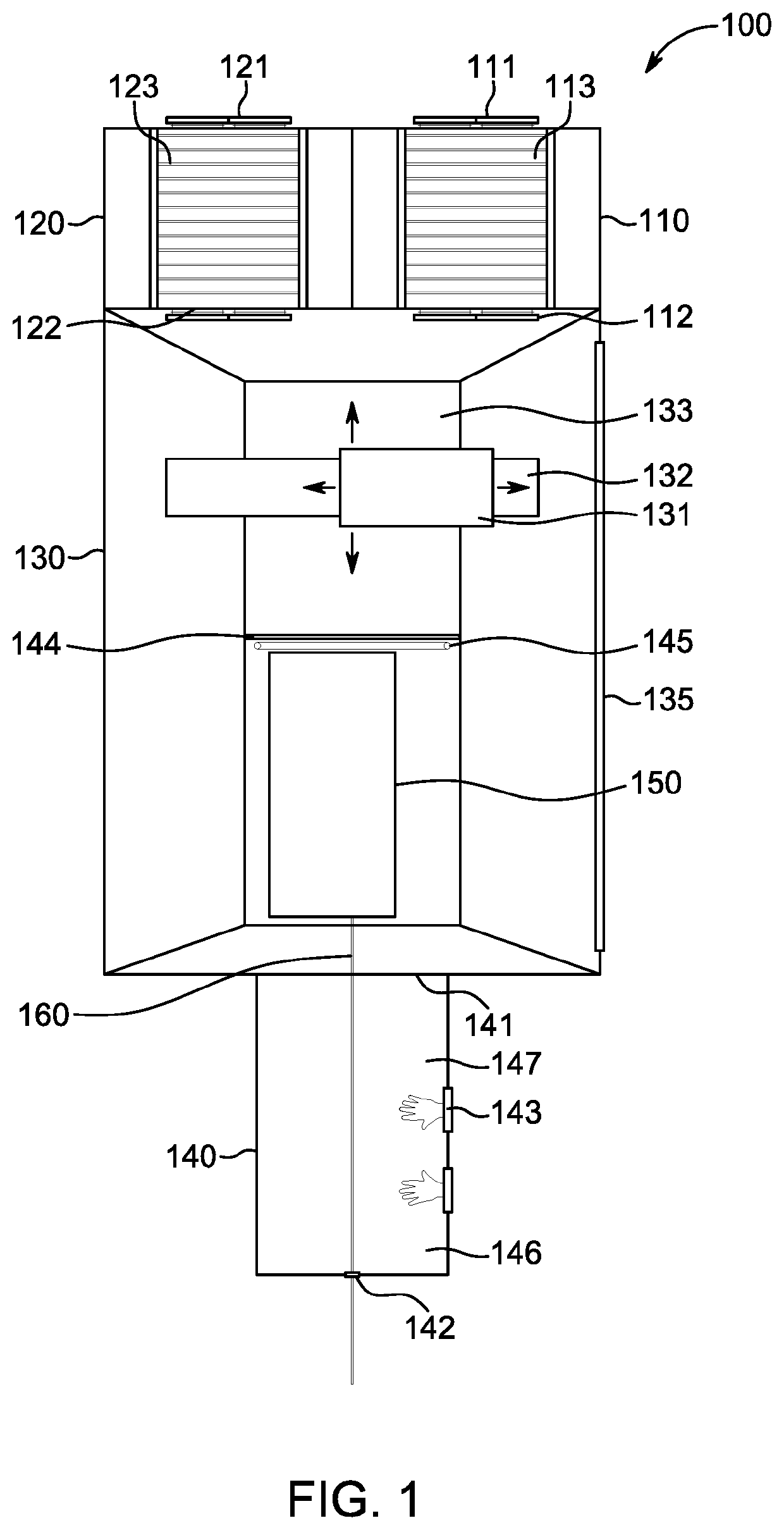
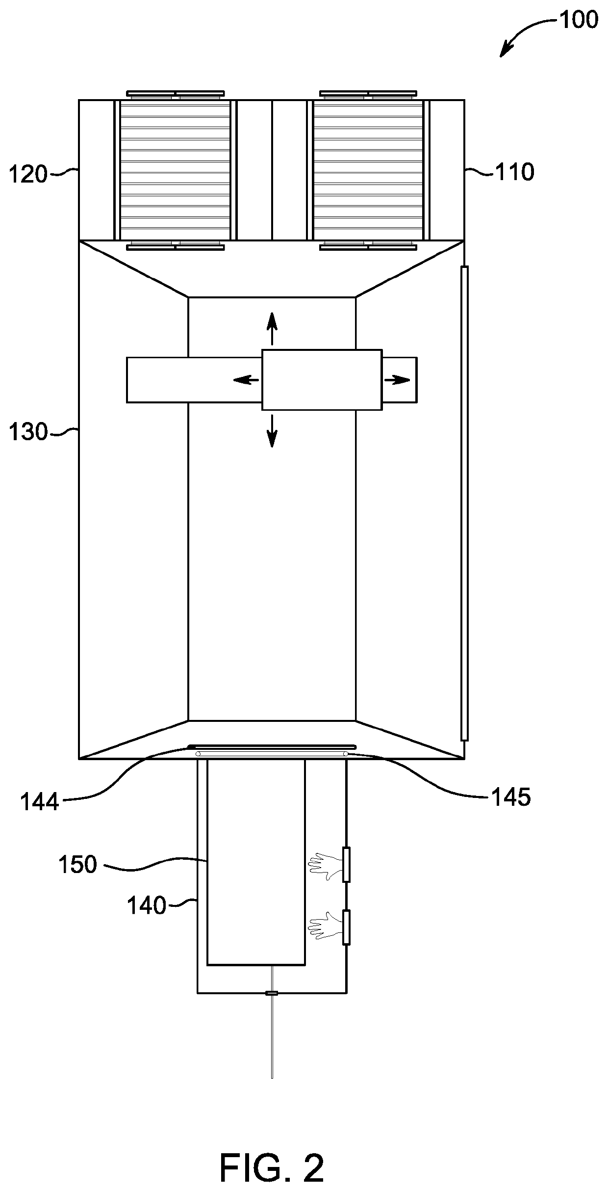
Provided is a chamber system for solid free form fabrication, the chamber system having a deposition chamber, a service chamber and one or more loading / unloading chambers. The chamber system allows for a more efficient and cost effective process to service the deposition apparatus, load holding substrates, and unload workpieces without requiring having to adjust the atmosphere in the deposition chamber.

Description

FIELD OF THE INVENTION[0001]The present invention relates to a method and arrangement for manufacturing objects by solid freeform fabrication, especially titanium and titanium alloy objects.BACKGROUND OF THE INVENTION[0002]Metal parts having precise dimensional tolerances can be made of titanium or titanium alloys are conventionally made by casting, forging or machining from a billet. These techniques can require large lead times or high material use of the expensive titanium metal, or both, in the fabrication of the metal part.[0003]Fully dense physical objects may be made by a manufacturing technology known as rapid prototyping, rapid manufacturing, layered manufacturing, solid freeform fabrication (SFFF), additive fabrication, additive manufacturing and 3D printing. This technique employs computer aided design (CAD) software to first construct a virtual model of the object which is to be made, and then transform the virtual model into thin parallel slices or layers, usually horiz...

Claims


Application Information

Patent Timeline
Patent Type & Authority Patents(United States)
IPC IPC(8): B22F3/105C23C14/24C23C14/50
CPCC23C14/50B22F3/1055C23C14/24B22F2003/1057B22F2003/1056B22F2201/20Y02P10/25B22F2201/10B22F10/00B22F12/86B22F10/16B33Y10/00B33Y30/00B22F10/20B33Y50/02B22F10/322B22F10/10B22F10/30
Inventor FORSETH, TRONDVIGDAL, BREDERAMSLAND, ARNESTEINSVIK, SVEINHAUGEN, JØRGEN
Owner NORSK TITANIUM
Learn More