Rotor Blade for a Wind Turbine

Inactive Publication Date: 2019-01-24
WINFOOR
View PDF7 Cites 1 Cited by
  • Summary
  • Abstract
  • Description
  • Claims
  • Application Information

AI Technical Summary

Benefits of technology

[0009]It is an object of the invention to provide blades that may be relatively easy to transport, even for

Problems solved by technology

Therefore, a difference in pressure is formed, resulting in a force on the blade.
However, there are several problems associated with increasing the length of blades.
For instance, the mass of the blades, which increases rapidly with the length, causes the blades to be exerted to gravity loads and eventually there is a risk of fatigue failure due to the large mass of the blade.
The

Method used


Image

  • Rotor Blade for a Wind Turbine
  • Rotor Blade for a Wind Turbine
  • Rotor Blade for a Wind Turbine

Examples


Example

[0058]The present invention will now be described more fully hereinafter with reference to the accompanying drawings, in which currently preferred embodiments of the invention are shown. This invention may, however, be embodied in many different forms and should not be construed as limited to the embodiments set forth herein; rather, these embodiments are provided for thoroughness and completeness, and fully convey the scope of the invention to the skilled person.

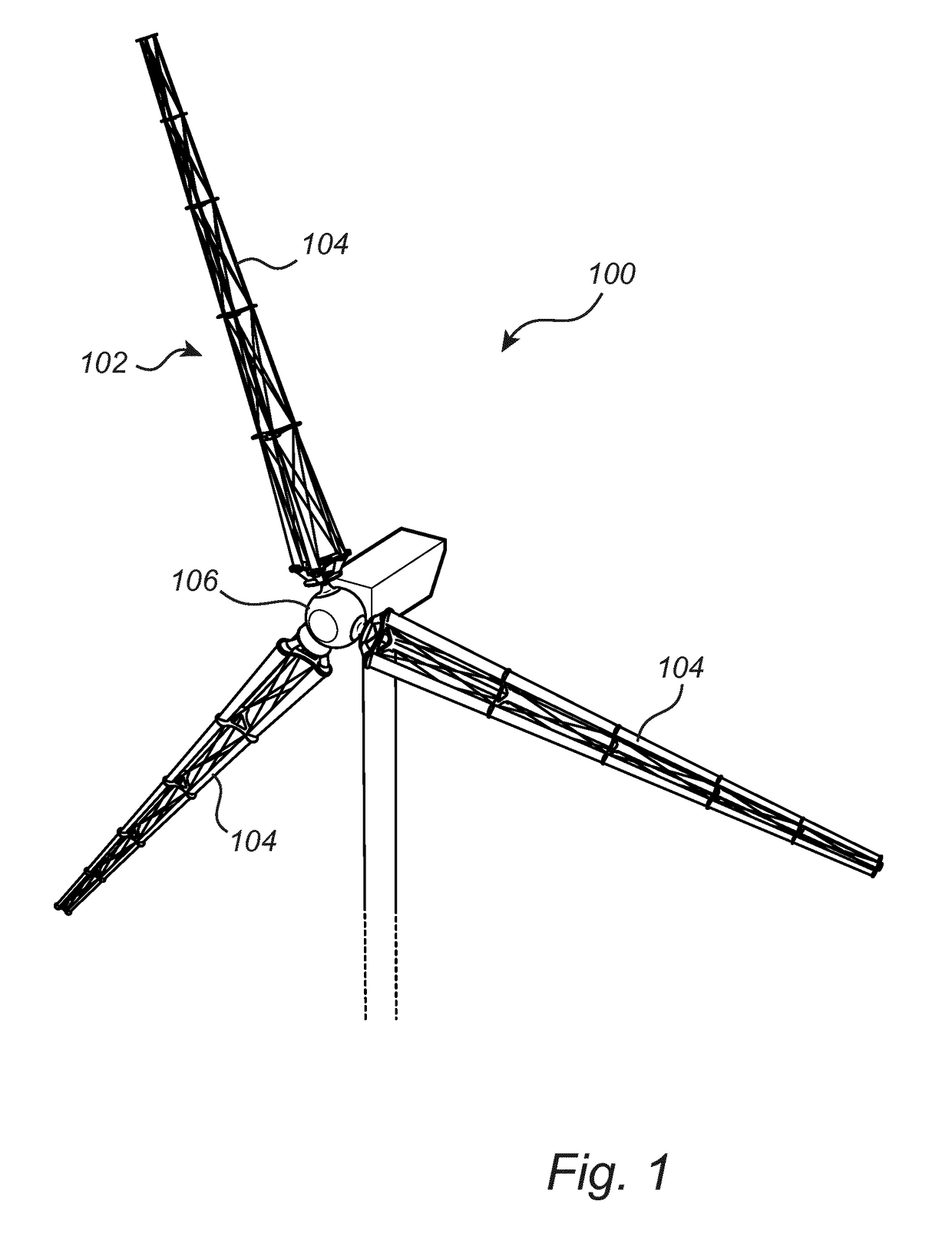
[0059]Referring now to FIG. 1, a horizontal-axis wind turbine 100 is shown. The wind turbine 100 comprises a rotor 102. The rotor 102 has rotor blades 104 and a central hub 106 to which the rotor blades 104 are attached such that the rotor blades 104 form cantilevered structures that are anchored only to the central hub 106. The rotor 102 captures energy of a mass of air that passes the rotor 102 due to a blowing wind. The energy is captured by means of the wind forcing the rotor blades 104 to bring the rotor 102 to rotate....


PUM


Abstract

The disclosure relates to a rotor blade (104) for a wind turbine, the rotor blade (104) comprising two or more wing members (110, 112, 114), wherein each wing member has an airfoil shaped cross-section as seen in a plane transverse to the longitudinal extension of the wing member, wherein each wing member (110, 112, 114) is divided into at least a first sub-member (110a) and a second sub-member (110b), the sub-members (110a-b) being arranged one after another along a longitudinal direction of the rotor blade (104), wherein, in each wing member (110, 112, 114), at an interface (116) between the first and the second sub-member (110a-b), the first sub-member (110a) is arranged in the rotor blade (104) with an outer end angular orientation about the longitudinal direction and the second sub-member (110b) is arranged in the rotor blade (104) with an inner end angular orientation about the longitudinal direction, the inner end angular orientation of the second sub-member (110b) being different from the outer end angular orientation of the first sub-member (110a). The disclosure also relates to a sub-member adapted to extend from an inner end to and outer end and to thereby form a discrete portion of a longitudinal extension of a wing member (110, 112, 114) of a rotor blade (104) for a wind turbine.

Description

FIELD OF INVENTION[0001]The invention relates to a rotor blade, which may be used in a wind turbine. The invention also relates to a sub-member adapted to extend from an inner end to and outer end and to thereby form a discrete portion of a longitudinal extension of a wing member of a rotor blade for a wind turbine.TECHNICAL BACKGROUND[0002]There is a growing interest in renewable energy technologies throughout the world. For instance, climate change concerns are driving energy production to renewable energy technologies. Wind power is therefore an important energy source and the amount of power produced annually through wind power is growing rapidly.[0003]Wind power is the conversion of wind energy into more useful forms, such as electricity. In this regard, use is made of a wind turbine, which is a device that converts kinetic energy from the wind into electrical power. A wind turbine comprises a rotor having a central hub, to which one or more blades are attached. The rotor is ar...

Claims


Application Information

Patent Timeline
IPC IPC(8): F03D1/06
CPCF03D1/0675F05B2280/6003F05B2240/302F05B2240/221F03D1/0633F05B2240/301Y02E10/72
Inventor BERTHILSSON, RIKARDWEDDIG, BJORNPESLIAKAS, GERARDO
Owner WINFOOR
Why Eureka
Try Eureka