Fan module with variable-pitch blades for a turbine engine

a turbine engine and variable-pitch technology, which is applied in the direction of machines/engines, liquid fuel engines, rotors, etc., can solve the problems of limiting the clearance at the tip of the fan blade, affecting the operation of variable-pitch systems, and affecting the operation of turbine engines

Active Publication Date: 2019-01-24
SN DETUDE & DE CONSTR DE MOTEURS DAVIATION S N E C M A
View PDF3 Cites 5 Cited by
  • Summary
  • Abstract
  • Description
  • Claims
  • Application Information

AI Technical Summary

Problems solved by technology

However, in the aforementioned documents, the pitch changing and control devices are related to open rotors that have a high hub-to-tip ratio and lack rigidity during rotation of the rotor.
This makes it more difficult to hold the rotating fan rotor in the turbo engine casing.
Additionally, variable-pitch systems may not function properly if the fan rotor is not held in a sufficiently rigid position, where such systems contain connections between parts of different diameters, or stator and rotor parts.
Another aspect of this configuration is that it limits the clearance at the tip of the fan blades.
Since the elastic return means exert their force in between two non-rotating parts, they themselves remain static, thereby limiting the rotating mass.

Method used


Image

  • Fan module with variable-pitch blades for a turbine engine
  • Fan module with variable-pitch blades for a turbine engine
  • Fan module with variable-pitch blades for a turbine engine

Examples


first embodiment

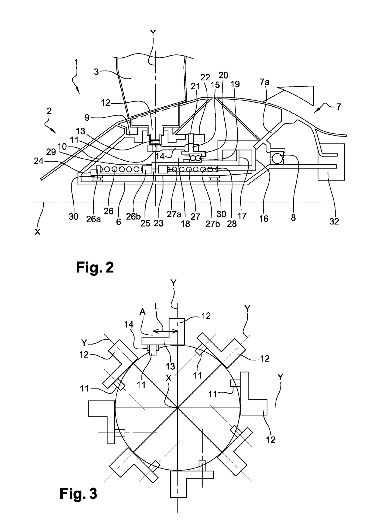
[0041] with reference to FIG. 2 in this configuration, the rotor 2 also comprises a support ring 9 for the blades 3, located ahead of the bearing 8. The front of the support ring 9 is linked to the front of the rotor 2 by a substantially truncated part 10 and the assembly is configured such that there is free interior space in front of the bearing 8, between the support ring 9 and the shaft 6. The ring 9 is radially located as close as possible to the shaft 6.

[0042]As illustrated on FIG. 2, a blade 3 is moveably mounted on the support ring 9 rotating around a substantially radial Y axis, by means of a rolling bearing, for instance (not illustrated). The blade 3 comprises a shaft 12 forming the blade foot centred on the Y axis, which projects radially beyond the support ring 9 in the free interior space. This shaft 12 allows the blade to rotate. As clearly illustrated, the ring 9 accommodates the blade foot shafts 12.

[0043]With reference to FIGS. 2 and 3, a crank 13 secured to the sh...

second embodiment

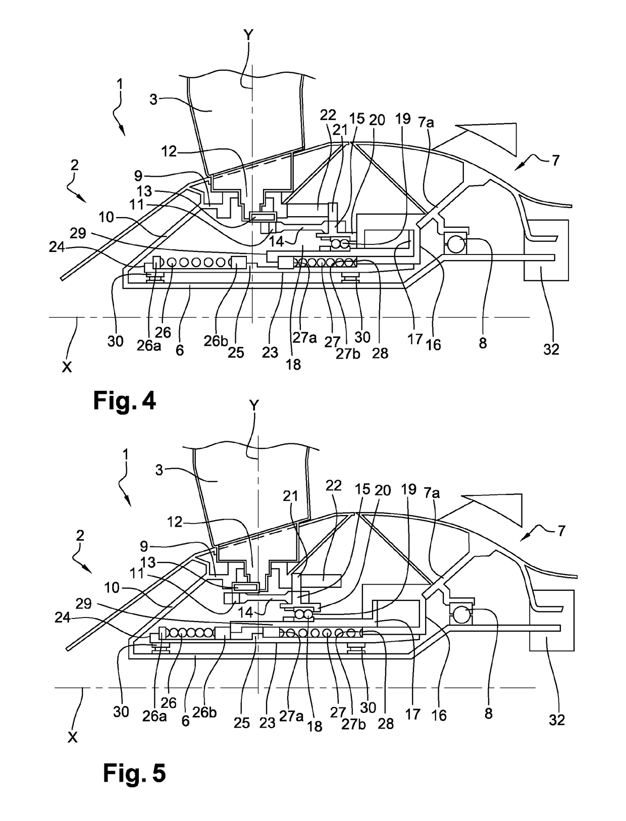
[0071]In a second embodiment, with reference to FIG. 6, the cylinder housing 16 is used, which housing is attached secured in front of the first retention bearing 8 of the rotor 2 on the part 7a of the stationary casing 7. Preferably, the housing 16 has an annular shape, especially its outer radial wall. A rear race 9b of the blades support ring 9 is arranged such that it is connected to the outer radial wall of the hydraulic cylinder housing 16 by a bearing 31 that enables it to rotate around the said wall.

[0072]The bearing 31 is mounted inversely relative to the bearing 8: the rotor 2 carrying the outer race of the bearing 31, whereas it carries the inner race of the bearing 8 on the shaft 6.

[0073]Here, the rotor 2, comprising the shaft 6, the conical connecting piece 10 and the support ring 9 together with the rear race 9a, for a pin of sorts that fits into the annular race 23 and encloses the stator composed of the fixed actuator up to the cylinder chamber 16, on the part 7a.

[0...


PUM


Abstract

A ducted fan module with variable-pitch blades for a turbo engine includes a rotor carrying a plurality of blades, a stationary casing and a pitch changing and control system for adjusting and controlling the setting of the blades. The rotor includes a central shaft and a blade support ring surrounding the central shaft, a front end of the ring that is connected to a front end of the central shaft, so as to create a rearward-opening annular space between the ring and the shaft. The annular space of the rotor housing the blade changing and control system and the central shaft are guided by a first bearing mounted in a stationary casing behind the ring. The fan has a tubular part connected to the stationary casing and extending into the annular space in front of the first bearing and carrying at least a first complementary bearing for guiding the shaft.

Description

FIELD OF THE INVENTION[0001]The invention relates to a turbo-engine fan with variable-pitch blades. More specifically, it involves holding the rotor of this fan.PRIOR ART[0002]The variable pitch of a turbo-engine fan is a means of boosting performance in various flight conditions. Additionally, the variable pitch may be advantageous in placing the blades in a feathered position, i.e. where they do not exert any thrust on the air even as the fan rotates, and then in a position where the thrust of the fan is reversed, without changing its rotation direction. The feathered position is a middle position of the blade pitch angle between the propulsion and reverse thrust modes.[0003]The following documents are known to have been presented by the applicant requesting the variable-pitch blades: FR-B1-3009710, US-A1-2014 / 0205457 and FR-A1-2980770. The blades are pivotally mounted around radial axes on a fan rotor support ring. The blade pitch changing and control devices include a system of ...

Claims


Application Information

Patent Timeline
Patent Type & Authority Applications(United States)
IPC IPC(8): F04D29/36F04D29/32F04D29/059F01D7/00F02K3/06
CPCF04D29/362F04D29/325F04D29/059F01D7/00F02K3/06F05D2260/79F05D2270/64F05D2220/36B64C11/385F04D29/056F04D29/323F01D25/16Y02T50/60F01D17/10
Inventor MORREALE, SERGE RENEBENSLAMA, YANISDIEVART, JEREMYIGEL, DOMINIK
Owner SN DETUDE & DE CONSTR DE MOTEURS DAVIATION S N E C M A
Why Eureka
Try Eureka