Valve apparatus
a valve and valve body technology, applied in the direction of valve operating means/release devices, electric control, machines/engines, etc., can solve the problems of large physical size and complicated configuration of fuel injection valves
- Summary
- Abstract
- Description
- Claims
- Application Information
AI Technical Summary
Benefits of technology
Problems solved by technology
Method used
Image

Examples
first embodiment
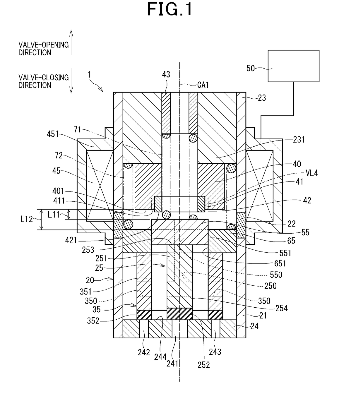
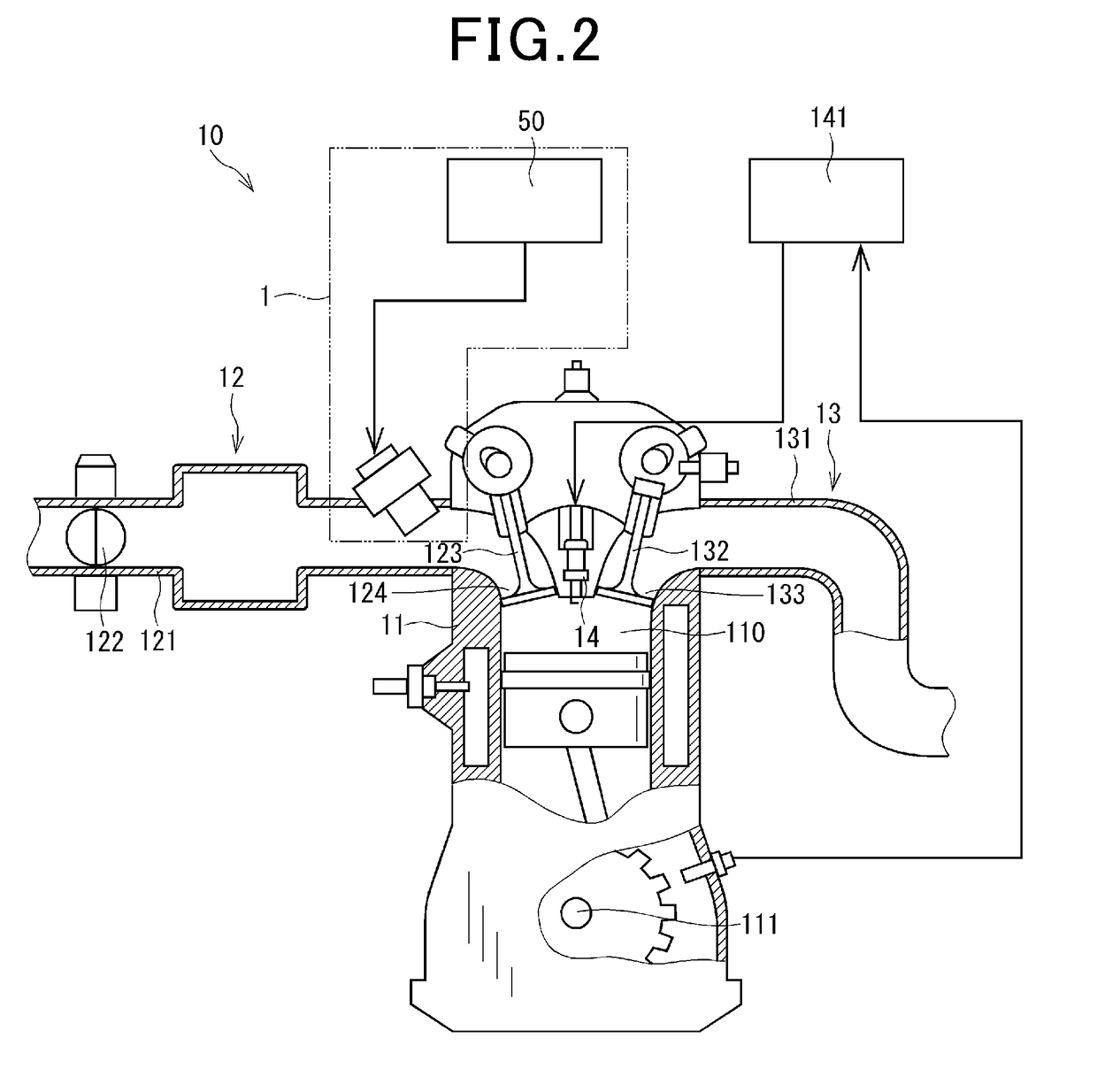
[0046]A fuel injection valve 1 that serves as a valve apparatus according to a first embodiment will be described with reference to FIG. 1 to FIG. 7. The fuel injection valve 1 is applied to an engine system 10 shown in FIG. 2.
[0047]First, a configuration of the engine system 10 will be described with reference to FIG. 2. For example, the engine system 10 includes a four-stroke engine 11. The engine system 10 generates rotational torque by burning fuel gas in a combustion chamber 110. The fuel gas serves as a fluid that is injected from the fuel injection valve 1. As shown in FIG. 2, the engine system 10 includes the engine 11, an intake system 12, the fuel injection valve 1, an exhaust system 13, a spark plug 14, and the like.
[0048]The intake system 12 includes an intake manifold 121, a throttle valve 122, and an intake valve 123. The throttle valve 122 is provided in the intake manifold 121. The throttle valve 122 is capable adjusting an amount of air that is supplied to the combu...
second embodiment
[0105]Next, a valve apparatus according to a second embodiment will be described with reference to FIG. 8. The second embodiment differs from the first embodiment in that the shock absorbing member is not provided in the magnetic constriction portion.
[0106]A fuel injection valve 2 according to the second embodiment includes the housing 20, the inner valve member 25, the outer valve member 35, the fixed core 40, a magnetic constriction portion 81, the coil 45, the control unit 50, the inner movable core 55, the outer movable core 65, the first spring 71, and the second spring 72.
[0107]The magnetic constriction portion 81 is provided on the valve-closing direction side of the fixed core 40. The magnetic constriction portion 81 is formed into an annular shape. The magnetic constriction portion 81 is formed such that an inner diameter thereof is larger than the inner diameter of the fixed core 40. A space 82 is provided on the inner side of the magnetic constriction portion 81 in the ra...
third embodiment
[0111]Next a valve apparatus according to a third embodiment will be described with reference to FIG. 9 to FIG. 12. The third embodiment differs from the first embodiment in terms of the shape of the inner valve member and the shape of the outer valve member. The third embodiment also differs from the first embodiment in that a third urging member is provided.
[0112]A fuel injection valve 3 according to the third embodiment includes the housing 20, an inner valve member 26, an outer valve member 36, the fixed core 40, the magnetic constriction portion 41, the coil 45, the control unit 50, the inner movable core 55, the outer movable core 65, the first spring 71, the second spring 72, and a third spring 73. The inner valve member 26 serves as a first valve member. The outer valve member 36 serves as a second valve member. The third spring 73 serves as an urging member.
[0113]The inner valve member 26 is a substantially rod-shaped member. The inner valve member 26 includes the shaft por...
PUM
 Abstract
Description
Claims
Application Information
 - R&D
- Intellectual Property
- Life Sciences
- Materials
- Tech Scout
- Unparalleled Data Quality
- Higher Quality Content
- 60% Fewer Hallucinations
Browse by: Latest US Patents, China's latest patents, Technical Efficacy Thesaurus, Application Domain, Technology Topic, Popular Technical Reports.
© 2025 PatSnap. All rights reserved.Legal|Privacy policy|Modern Slavery Act Transparency Statement|Sitemap|About US| Contact US: help@patsnap.com