Control of color primaries and white point in a laser-phosphor projector

a projector and laser-phosphor technology, applied in the field of optical sub-assembly, a projector, can solve the problems of color splitting and recombination engines, similar problems can occur, etc., and achieve the effect of reducing or minimizing the loss of ligh

Active Publication Date: 2019-01-31
BARCO NV
View PDF0 Cites 10 Cited by
  • Summary
  • Abstract
  • Description
  • Claims
  • Application Information

AI Technical Summary

Benefits of technology

[0025]An object of the present invention is to provide an optical subassembly for a projector designed to work, for example optionally with a red laser and a phosphor source with the advantage of reducing or minimizing the losses. Embodiments of the present invention reduce or minimize the losses of light which occur if a yellow phosphor is used for example. These losses can happen at different stages in the optical path such as in the Philips prism, due to electronic correction, due to a notch filter and / or any combination or all of these. Similar problems can occur with other color splitting and recombination engines for 3-chip projectors, DLP or also LCOS or LCD, for instance with a color splitting dichroic mirrors and a recombination X-cube.
[0026]Embodiments of the present invention provide the advantage of a smaller, more compact, less expensive projector with a lower need for cooling, specifically for a wide-gamut colour performance. Embodiments of the present invention are specifically suited for a specific standardized white color point such as a DCI white colour point.
[0027]An advantage of embodiments of the present invention is to match the color performance of the projection system to a color gamut target as given by DCI or larger with low or minimal light losses.

Problems solved by technology

Similar problems can occur with other color splitting and recombination engines for 3-chip projectors, DLP or also LCOS or LCD, for instance with a color splitting dichroic mirrors and a recombination X-cube.

Method used


Image

  • Control of color primaries and white point in a laser-phosphor projector
  • Control of color primaries and white point in a laser-phosphor projector
  • Control of color primaries and white point in a laser-phosphor projector

Examples


second embodiment

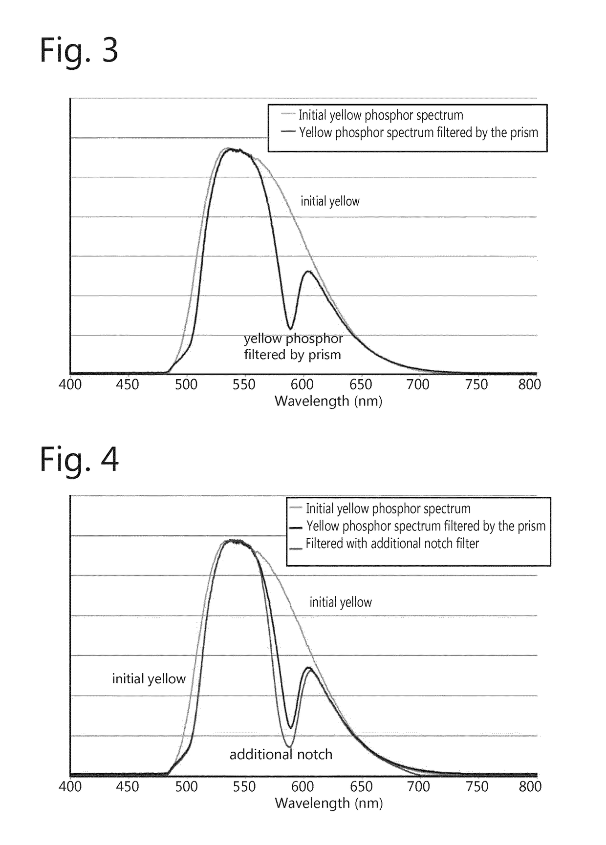
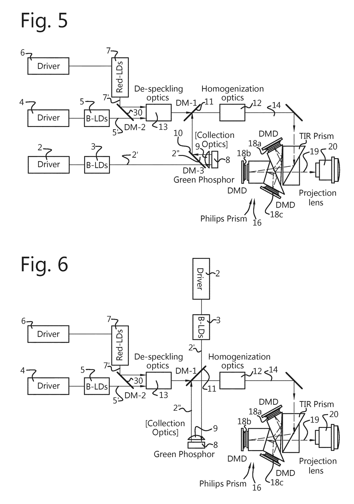
[0360]In accordance with a second embodiment according to the present invention, the wavelength conversion element 8 shown in FIG. 5 or in FIG. 6 can be a yellow phosphor, in which case the light emitted by the conversion element has a spectrum similar to state of the art projectors, as the one illustrated in FIG. 3.

[0361]The yellow phosphor is responsible for the generation of the primary red and green, however, with an excess of green and intermediate wavelengths located between the primary green and red, leading to a desaturation of primary colors as described previously. However, an important distinction with respect to prior art projectors pertains to the use of two independent lasers for the generation of the blue primary color and for exciting the wavelength conversion element, thereby increasing the number of degrees of freedom for controlling the white point of the projector.

[0362]As the red primary color is provided by the wavelength conversion element, the red laser becom...


PUM


Abstract

A light projection system for generating an image with three primary colors, each primary color being respectively defined by a first, second and third wavebands. The system includes a first blue laser source emitting a first beam in a fourth waveband, the first blue laser source having a first laser driver, a second blue laser source emitting a second beam having a central wavelength and a fifth waveband, the second blue laser source having a second laser driver, a substrate having a wavelength conversion element for emitting light at a plurality of wavelengths after absorption of a light beam at an excitation wavelength within a fifth waveband of the second blue laser source and a beam combiner for combining the combined first beam and the converted beam, which combination results in a white beam. Dichroic losses can be reduced by using a green phosphor together with red laser assistance.

Description

BACKGROUND[0001]The present invention relates to an optical sub-assembly, a projector and method of operating a projector, a controller for controlling a projector and a method of controlling a projector.[0002]Projection technology makes increasing use of solid state light sources instead of the conventional lamps, e.g. using lasers in a single-chip DLP projector, in three-chip DLP projectors or in other projectors with 3 imagers (LCD, LCoS, . . . ).[0003]Laser-based solid state projectors could be classified in two main categories:[0004]Full laser projectors (using direct red, green and blue lasers)[0005]Laser phosphor projectors (using blue laser to excite a wavelength convertor material to generate some of the three primaries)[0006]Currently, the full laser projectors are typically ultra-bright projectors aimed at the niche market of digital cinema (DC). Laser phosphor projectors mainly have a lower light output, i.e. under 12,000 lumens and therefore are sold in the markets outs...

Claims


Application Information

Patent Timeline
Patent Type & Authority Applications(United States)
IPC IPC(8): H04N9/31G02B27/10G03B21/20
CPCH04N9/3182G02B27/1006G03B21/204G03B21/206H04N9/3105H04N9/3158H04N9/3161H04N9/3194G03B21/2013C09K11/7774
Inventor TARPAN, MIHAELACHEDAD, ALLELMAXIMUS, BARTCOULIER, NICO
Owner BARCO NV
Why Eureka
Try Eureka