Method for manufacturing spark plug

a manufacturing method and spark plug technology, applied in the manufacture of spark plugs, spark plugs, electrical appliances, etc., can solve the problems of difficult to reduce increase the position of the starting point, etc., and achieve the effect of reducing the dimensional tolerance of the spark gap, high accuracy, and easy ben

Inactive Publication Date: 2019-02-07
NGK SPARK PLUG CO LTD +1
View PDF8 Cites 0 Cited by
  • Summary
  • Abstract
  • Description
  • Claims
  • Application Information

AI Technical Summary

Benefits of technology

[0006]In accordance with a first aspect of the present invention, there is provided a method for manufacturing a spark plug including: a tubular metal shell extending in a direction of an axial line from a front side toward a rear side; an insulator disposed in a tube hole of the metal shell and holding a center electrode at the front side; and a rod-like ground electrode having a first end portion joined to a front end portion of the metal shell, and having a second end portion bent to an axial line side so as to be opposed to the center electrode. The method for manufacturing the spark plug according to the present invention includes: a preparation step of preparing the metal shell having the ground electrode joined thereto; and a bending step of bending the ground electrode joined to the metal shell, along a first die to the axial line side. The first die has: an end portion to be pressed against an inner surface of the ground electrode; and a flat surface portion contiguous to the end portion via a curved portion bulging outward. The flat surface portion is formed so as to be orthogonal to the axial line or so as to be tilted to a first end portion side, toward the inner surface of the ground electrode. The bending step includes a first step of pressing the end portion of the first die against the ground electrode.
[0007]In the method for manufacturing the spark plug according to the first aspect, the end portion of the first die is pressed against the ground electrode joined to the metal shell by the first step of the bending step. The first die has the end portion to be pressed against the inner surface of the ground electrode, and the flat surface portion contiguous to the end portion via the curved portion bulging outward. The flat surface portion is formed so as to be orthogonal to the axial line or so as to be tilted to the first end portion side, toward the inner surface of the ground electrode. Since the ground electrode is bent along the first die to the axial line side by the bending step, a starting point from which the ground electrode starts to be bent is determined in accordance with the end portion of the first die. Therefore, a dimensional tolerance for the spark gap can be reduced.
[0008]In accordance with a second aspect of the present invention, there is provided a method for manufacturing the spark plug as described above, wherein the ground electrode is bent with use of a second die which is a roller in a second step. The second die is rolled on an outer surface, of the ground electrode, which is a surface on a side opposite to the inner surface toward the second end portion while pressing the outer surface, such that the ground electrode is fitted along the flat surface portion with the end portion of the first die acting as a fulcrum. A position at which the second die is first pressed against the ground electrode in the second step is a position that is closer, in the direction of the axial line, to the second end portion than a position at which the end portion of the first die is pressed. Therefore, in addition to the effect in the first aspect, the ground electrode can be prevented from being squashed between the first die and the second die when the second die is first pressed against the ground electrode.
[0009]In accordance with a third aspect of the present invention, there is provided a method for manufacturing the spark plug as described above, wherein the position at which the second die is first pressed against the ground electrode in the second step is a position that is closer, in the direction of the axial line, to the second end portion than a boundary between the curved portion and the flat surface portion. The distance between the end portion of the first die and the position at which the second die is first pressed against the ground electrode, can be elongated as compared with a case where the position at which the second die is first pressed against the ground electrode is a position that is closer, in the direction of the axial line, to the first end portion than the boundary between the curved portion and the flat surface portion. Therefore, in addition to the effect in the second aspect, the ground electrode can be easily bent with the end portion of the first die acting as a fulcrum.
[0010]In accordance with a fourth aspect of the present invention, there is provided a method for manufacturing the spark plug as described above, wherein the position at which the second die is first pressed against the ground electrode in the second step is a position that is closer to the first end portion than a position in the direction of the axial line at which an end on a second end portion side of the ground electrode is to be located when an entirety of a part, of the inner surface of the ground electrode, from a position of contact with the end portion of the first die to an end on the second end portion side comes into contact with the first die. As a result, the ground electrode can be pressed against the first die from the first end portion side to the second end portion side, whereby the ground electrode can be bent with high accuracy so as to be fitted along the first die in addition to the effect in the second or third aspect.

Problems solved by technology

However, with the above-described conventional technique, a starting point from which the ground electrode starts to be bent is not determined, and thus, variation in the position of the starting point is increased.
A problem arises that it is difficult to reduce a dimensional tolerance for the spark gap, owing to the degree of the variation.

Method used


Image

  • Method for manufacturing spark plug
  • Method for manufacturing spark plug
  • Method for manufacturing spark plug

Examples


Embodiment Construction

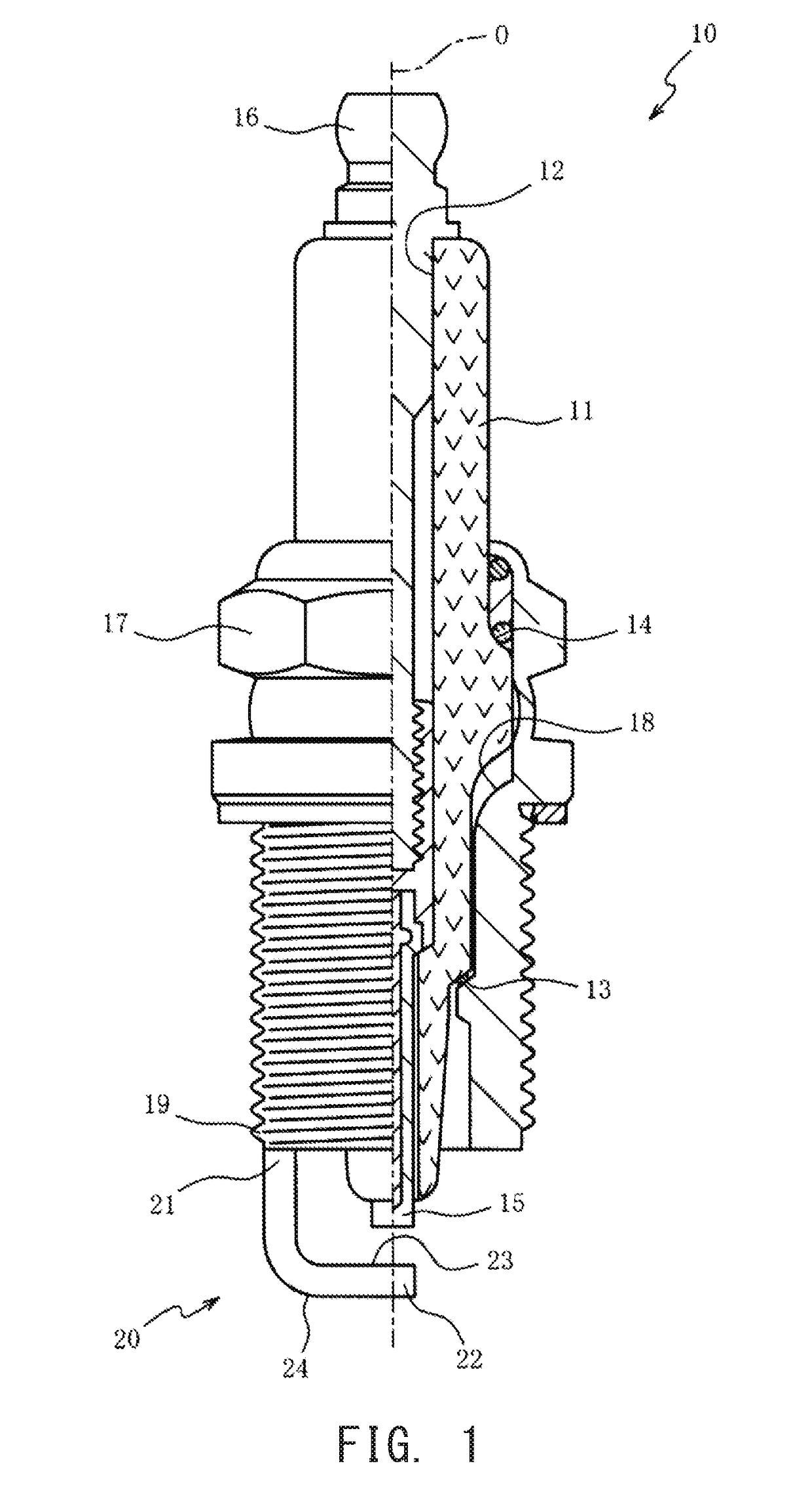
[0017]Hereinafter, preferred embodiments of the present invention will be described with reference to the accompanying drawings. FIG. 1 is a half sectional view of a spark plug 10 according to one embodiment of the present invention, with an axial line O thereof as a boundary. In FIG. 1, the lower side of the drawing sheet is referred to as a front side of the spark plug 10, and the upper side of the drawing sheet is referred to as a rear side of the spark plug 10. The spark plug 10 includes an insulator 11, a center electrode 15, a metal shell 17, and a ground electrode 20.

[0018]The insulator 11 is a cylindrical member formed from alumina or the like having excellent mechanical property and insulation property at high temperature, and has an axial hole 12 formed so as to penetrate therethrough along the axial line O. The insulator 11 has an outer circumferential surface on which a first fitted portion 13 which is a tilted surface facing the front side and a second fitted portion 14...


PUM


Abstract

A method for manufacturing the spark plug comprising bending a ground electrode that is joined to a metal shell, along a first die, the first die having an end portion to be pressed against an inner surface of the ground electrode, and a flat surface portion contiguous to the end portion via a curved portion bulging outward, the flat surface portion being formed to be orthogonal to an axial line and includes a first step of pressing the end portion of the first die against the ground electrode.

Description

RELATED APPLICATIONS[0001]This application claims the benefit of Japanese Patent Application No. 2017-148826, filed Aug. 1, 2017, the entire content of which is incorporated herein by reference.FIELD OF THE INVENTION[0002]The present invention relates to a method for manufacturing a spark plug, and particularly to a method for manufacturing a spark plug including a bent ground electrode.BACKGROUND OF THE INVENTION[0003]In a general spark plug mounted to an internal combustion engine, a bent ground electrode joined to a metal shell and a center electrode are opposed to each other with a spark gap interposed therebetween. The dimension of the spark gap influences a required voltage for causing a spark discharge, and thus, it is desirable that a dimensional tolerance for the spark gap is small. Japanese Patent Application Laid-Open (kokai) No. 2014-157769 discloses a technique in which a first die is disposed at a distance from the inner surface of a ground electrode, and a second die ...

Claims


Application Information

Patent Timeline
Patent Type & Authority Applications(United States)
IPC IPC(8): H01T21/02H01T13/32H01T13/39
CPCH01T21/02H01T13/32H01T13/39
Inventor ITO, TAKESHIKACHIKAWA, NORIHIDE
Owner NGK SPARK PLUG CO LTD
Why Eureka
Try Eureka