Chair and seat support mechanism

a support mechanism and chair technology, applied in the field of chairs, can solve the problems of difficult to say that it is possible to provide supports properly corresponding, caster may run in an unexpected direction, and the stability of the chair is difficult to achieve, so as to achieve the effect of maintaining high work efficiency

Active Publication Date: 2019-02-14
KOKUYO CO LTD
View PDF0 Cites 16 Cited by
  • Summary
  • Abstract
  • Description
  • Claims
  • Application Information

AI Technical Summary

Benefits of technology

[0040]With the above-described configuration, the present invention can provide a chair in which the seated person can perceive a comfortable sitting feeling even if sitting for a long time, and a high work efficiency can stably be maintained.

Problems solved by technology

Thus, it would be difficult to say that it is possible to provide supports properly corresponding to the body movement of the seated person.
Further, when the seated person braces his / her feet to the floor, if a lower end of a leg is supported by a caster, the caster may run in an unexpected direction, making a stable use of the chair difficult.
In particular, the seat only performs a pivotal operation via the supporting post around the lower end being a fulcrum, and therefore, a seat pivotal trajectory is not accorded with a movement below the knees of the seated person, resulting in an undesirable support state in which the feet get stuck when the seat inclines forward.
Further, the support mechanism has a structure in which the supporting post descends and the lower end thereof comes in contact with the floor when the seated person sits down on the chair, and thus, there is inconvenience in that the seat sinks every time the persons sits down, leading to a problem that the floor can easily be damaged when the supporting post swings while being in contact with the floor.

Method used


Image

  • Chair and seat support mechanism
  • Chair and seat support mechanism
  • Chair and seat support mechanism

Examples


first embodiment

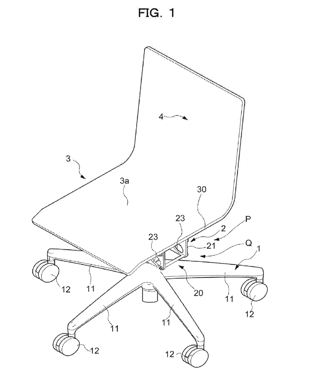
[0076]A chair according to a first embodiment of the present invention is referred to as an office rotating chair that can suitably be used in an office or at home.

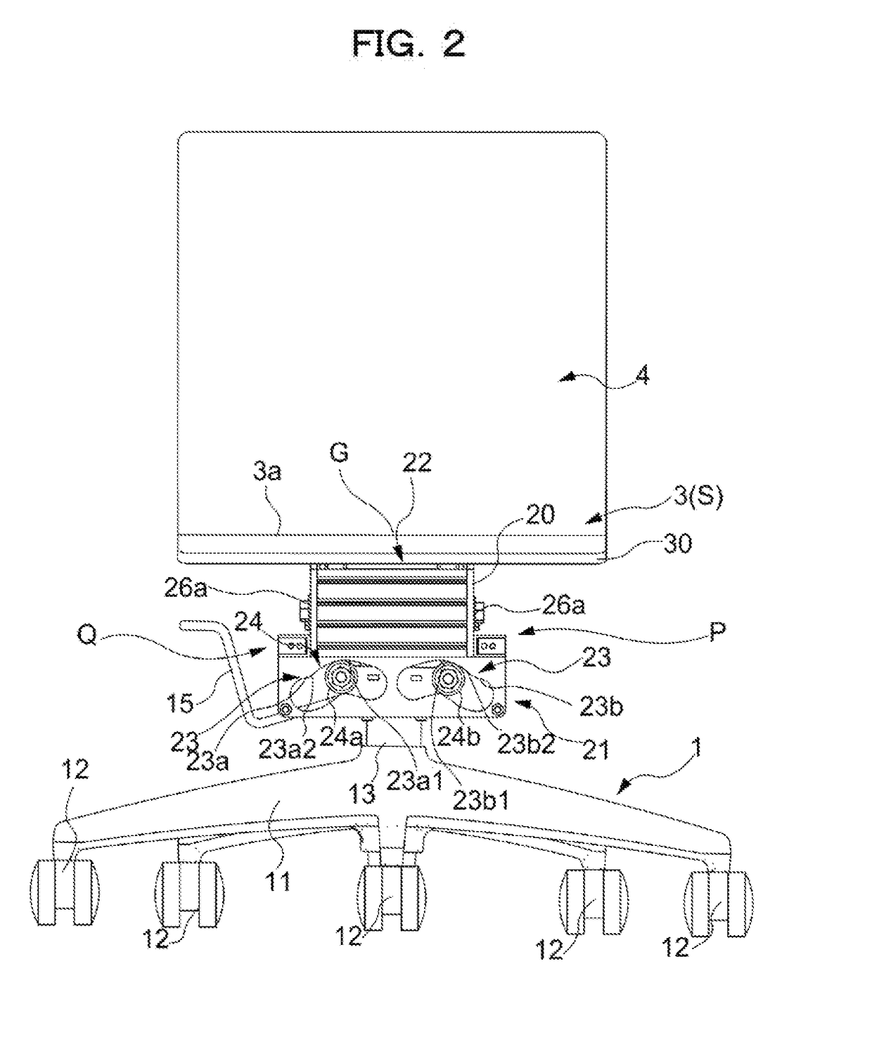
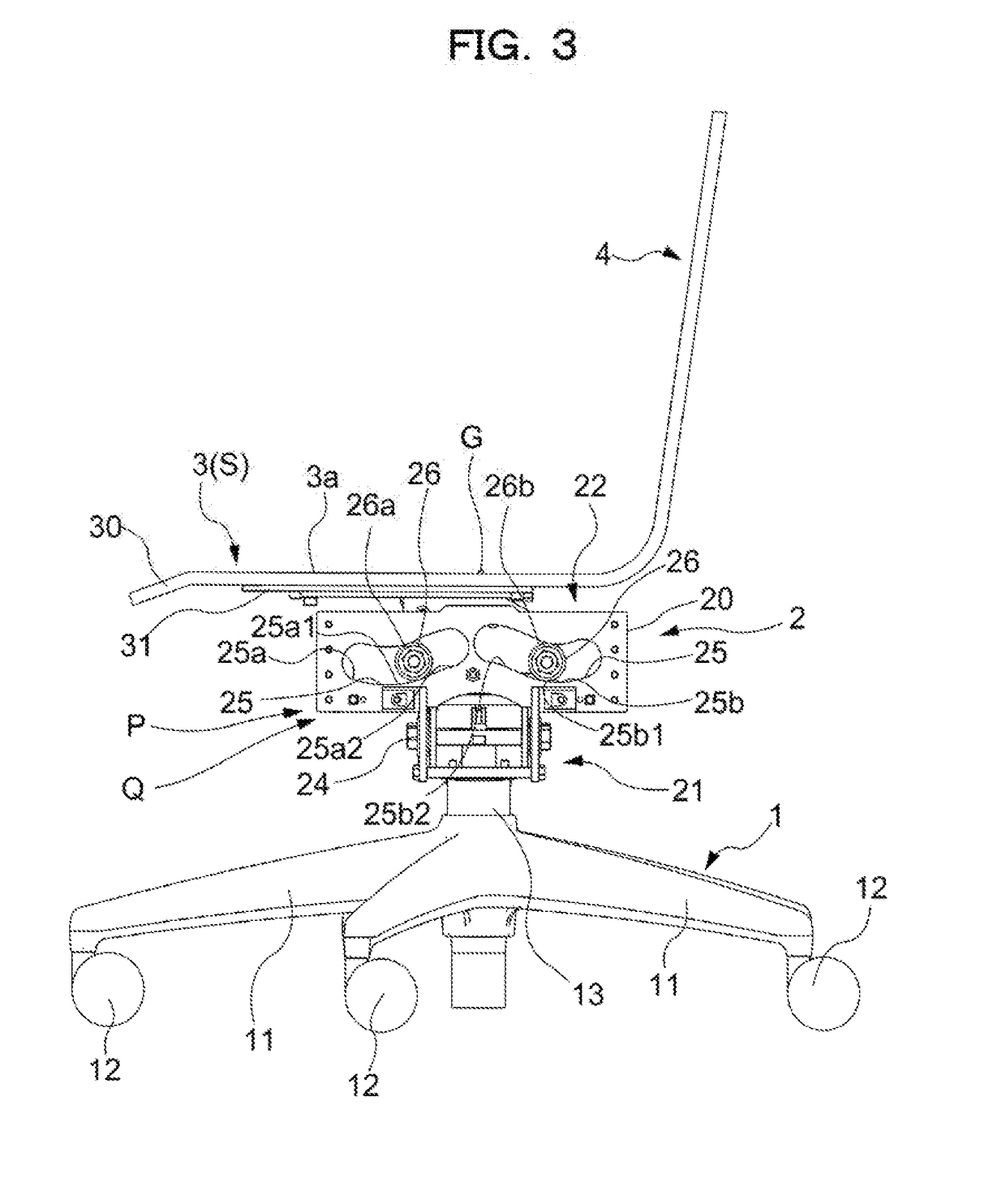
[0077]As illustrated in FIG. 1 to FIG. 8, the chair mainly includes: a leg 1 erected on a floor surface, a seat 3 arranged above the leg 1, and a backrest 4 formed integrally with the seat 3.

[0078]The leg 1 includes a leg vane 11 formed radially in plan view; a caster 12 attached to a bottom side of the leg vane 11 and roll ably contacting the floor surface; a leg supporting post 13 erected on a center of the leg vane 11; a gas spring 14 being a lifting up and down mechanism mounted within the leg supporting post 13 and configured to support the seat 3 in a lifting up and down manner, a rotation support mechanism 16 configured to support, in the vicinity of an upper end of the leg supporting post 13, the seat 3 to permit horizontal rotation by allowing a rod of the gas spring 14 to relatively rotate with respect to the le...

second embodiment

[0127]A chair according a second embodiment of the present invention may be suitably utilized as an office rotating chair, similarly to that in the first embodiment described above.

[0128]That is, also in the chair according to the present embodiment, a support mechanism 5 interposed between the leg 1 and the seat 3 is arranged below the seat 3, is configured to movably support the seat 3, at least at two locations in the front-rear direction and two locations in the left-right direction, along a predetermined trajectory, includes a seat inclining mechanism Q being a seat inclining function configured to downwardly incline the tip side in a movement direction of the seat 3 in accordance with movement of the seat 3, and further includes a return-force generation mechanism configured to generate the return force in the direction of returning the seat 3 having moved from the reference position (S) in the front-rear or left-right direction, to the reference position (S).

[0129]Other than ...

third embodiment

[0148]Next, a third embodiment of the present invention will be described with reference to FIG. 23 to FIG. 26. In each of the above-described embodiments, as a structure allowing the seat 3 to operate forward and rearward or rightward and leftward, the structure based on the relative operation between the guide surfaces 23a, 23b, 25a, 25b, and the followers 24a, 24b, 26a, and 26b, and the structure based on the operation of the left-right link 55, the front link 58, and the rear link 59 are respectively disclosed. In contrast to these embodiments, in the present embodiment, a joint support, mechanism 6 in which the structure allowing the seat 3 to operate in the front-rear direction is used together with a structure based on a relative operation between the guide surface 25a and the follower 26a and a structure based on the operation of the rear link 59, is applied. That is, also in the chair according to the present embodiment, the joint support mechanism 6 interposed between the ...


PUM


Abstract

A chair includes a support mechanism 2 interposed between a leg 1 and a seat 3, wherein the support mechanism 2 is arranged below the seat 3, is configured to each individually and movably support the seat 3, at least at two locations in a front-rear direction and two locations in a left-right direction, along a predetermined trajectory, and the support mechanism 2 includes: a seat inclining mechanism Q or a seat inclining function configured to downwardly incline a tip side in a movement direction of the seat 3 in accordance with movement of the seat 3, and further includes: a center-of-gravity movement mechanism P or a return-force generation mechanism configured to generate a return force in a direction of returning the seat 3 having moved from a reference position (S) in a front-rear or left-right direction, to the reference position (S) by using a center-of-gravity movement.

Description

TECHNICAL FIELD[0001]The present invention relates to a chair suitably applicable to an office rotating chair and the like.BACKGROUND ART[0002]Conventionally, chairs, especially office rotating chairs, with an aim that a seated person can maintain a comfortable sitting posture for a long time in an office, at home or the like, have been widely devised (for example, see Patent Document 1).[0003]These office rotating chairs are configured so that a seat and a backrest can be tilted in accordance mainly with a rearward inclining and forward inclining movement of the seated person and are configured so that the seat and the backrest can be fixed in a position allowing for realization of a required posture of the seated person, so that an operation allowing the seated person to feel comfort while proceeding a work is possible.[0004]Even though, from an outside perspective, it may appear as if a seated person sitting on an office rotating chair for a long time normally rests in a posture ...

Claims


Application Information

Patent Timeline
Patent Type & Authority Applications(United States)
IPC IPC(8): A47C3/026A47C7/00A47C1/024
CPCA47C3/026A47C7/004A47C7/006A47C1/024A47C3/0257A47C3/18A47C3/20A47C3/0255
Inventor YAJIMA, TOSHIKISUGANO, TAKAOSHIBAMOTO, YASUHIROXU, FEI
Owner KOKUYO CO LTD
Why Eureka
Try Eureka