Machine for dispensing beverages from a pod, comprising a device for the synchronized injection of two volumes of air

a technology of beverage dispenser and pod, which is applied in the direction of positive displacement liquid engine, domestic application, kitchen equipment, etc., can solve the problems of preparing beverages with heterogeneous mixtures, and achieve the effect of avoiding water wastage and good food hygien

Active Publication Date: 2019-02-14
SEB SA
View PDF11 Cites 2 Cited by
  • Summary
  • Abstract
  • Description
  • Claims
  • Application Information

AI Technical Summary

Benefits of technology

[0021]During actuation of the piston causing the suction of the water in the chamber, the check valves ensure that the water contained in the tank will be drawn off without risk of suction of fluid from the outlet of the dispensing circuit. Conversely, during actuation of the piston causing the discharge of the water contained in the chamber, said check valves ensure that the water will be released by the outlet of the dispensing circuit, without possibility of water being discharged into the tank. In addition, this pump design guarantees precise and reproducible suction and discharge of the quantity of water, and the presence of said check valves means that said suction and discharge will not be marred by error.
[0022]In one embodiment of the dispensing machine, the water dispensing device comprises a system for purging a volume of water contained in the dispensing circuit, downstream from the first check valve. This prevents residual stagnant water from staying inside the dispensing circuit during a more or less prolonged period between two beverage preparations, so that a quality beverage is supplied at each dispensing, while adhering to good food hygiene.
[0023]In the presence of a purge system as noted above, the machine is configured so that the water pump discharges a volume of water, and the volume of purged water added to said volume of discharged water constitute the volume of water allowing the beverage to be prepared. Thus, the purge water takes part in the preparation of the beverage, which avoids water wastage and the need to add a purged water collecting vessel to the machine.

Problems solved by technology

This variation in concentration has the disadvantage of preparing a beverage with a heterogeneous mixture in the container.

Method used


Image

  • Machine for dispensing beverages from a pod, comprising a device for the synchronized injection of two volumes of air
  • Machine for dispensing beverages from a pod, comprising a device for the synchronized injection of two volumes of air
  • Machine for dispensing beverages from a pod, comprising a device for the synchronized injection of two volumes of air

Examples


Embodiment Construction

[0037]The machine 1 for dispensing beverages will be called “machine 1” in the rest of the description.

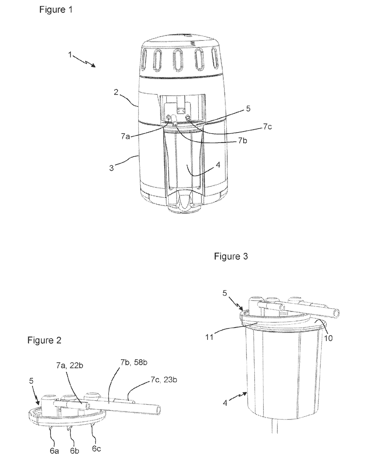
[0038]As illustrated in FIG. 1, the machine 1 comprises a frame 2 and a receptacle 3 for receiving a pod 4. The frame 2 includes a device (not illustrated) for moving a needle holder 5 which can be engaged on the pod 4, as illustrated in FIGS. 1 to 3. The receptacle 3 is articulated in relation to said frame 2 such that it can be arranged either in an open position, where the pod 4 can be inserted into the receptacle 3, or in a closed position, where the needle holder 5 can be engaged on the pod 4.

[0039]The needle holder 5 receives three needles 6a, 6b, 6c connected to conduits 7a, 7b, 7c allowing fluids to be dispensed. The number of needles and

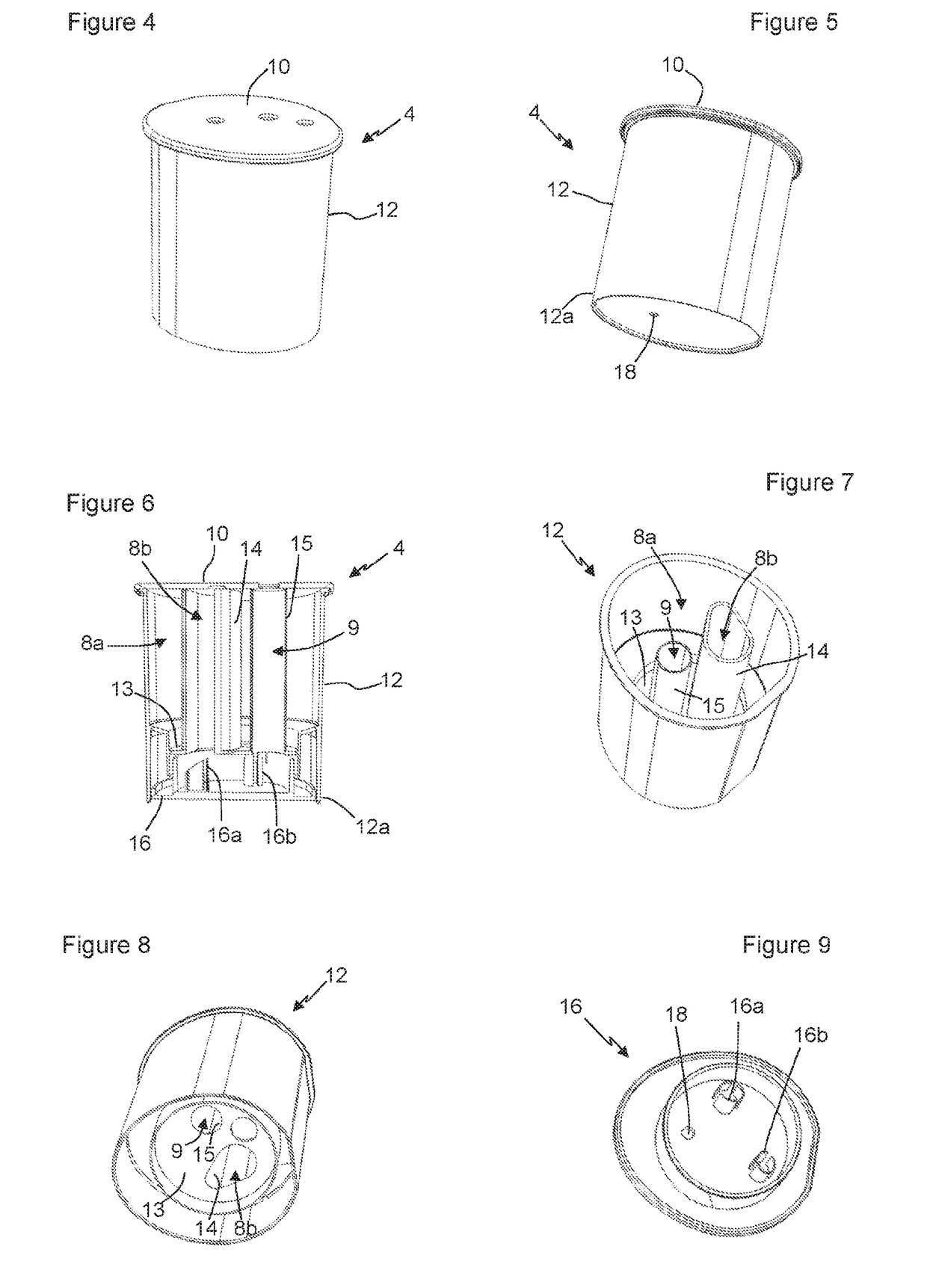
the types of fluids dispensed, in particular air or water, depend on the design of the pod 4. In this instance, the machine 1 is configured to receive a pod 4 comprising two cavities, 8a, 8b, each cavity containing an ingredient L1, L2 (dia...


PUM


Abstract

A machine for dispensing beverages includes a pod including at least two cavities each cavity containing a volume of ingredients forming part of a composition of the beverage, the machine further including an air injection device configured to supply at least two volumes of air in a synchronized manner, the at least two volumes of air being adapted respectively to the volumes of ingredients in the at least two cavities, the injection device including an air pump including two chambers and two pistons slidably mounted respectively in the two chambers, and an actuator configured to actuate the two pistons in a synchronized manner.

Description

[0001]This invention concerns a machine for dispensing beverages from a pod and has the principal objective of optimizing the dispensing of fluids during preparation of a beverage.[0002]“Pod” means a capsule comprising one or more cavities, each cavity containing an ingredient, in particular a liquid, forming part of the composition of the beverage, these ingredients being intended to be mixed with water during preparation of the beverage.[0003]In a particular embodiment, the pod consists of a capsule comprising several cavities, each cavity containing an ingredient, a channel allowing water to be dispensed, and a mixing chamber. The pod is configured to separate the mixing chamber from the cavities and from the channel, in an initial mode, and to cause the mixing chamber to communicate with the cavities and with the channel, in a beverage preparation mode. In addition, the machine comprises air injection means and water injection means, configured to perforate the pod and to inject...

Claims


Application Information

Patent Timeline
Patent Type & Authority Applications(United States)
IPC IPC(8): A47J31/40
CPCA47J31/407A47J31/405F04B13/02F04B3/003A47J31/32
Inventor BRIERE, MATTHIEURIVA, ARNAUDDOS SANTOS, QUENTIN
Owner SEB SA
Why Eureka
Try Eureka