
Fuel-containg fire-starting device

a fuel container and fire-starting technology, applied in the fuel industry, firelighters, fuels, etc., can solve the problems of not being able to solve everything, not being easy to realize, and usually not being able to quickly and efficiently solve the problem of fuel container failures

Active Publication Date: 2019-02-14
VILLARREAL VIVES JOSE ALEJANDRO +1
View PDF3 Cites 3 Cited by
  • Summary
  • Abstract
  • Description
  • Claims
  • Application Information

AI Technical Summary

Benefits of technology

The fire start fuel container device is a container that can be used to start a fire using a combination of fuel and air. The device has a removable upper part that allows air to flow through and mix with the fuel inside. The device also has a combustion body with a wick and liquid wax to start the fire. The main technical effect of the device is to provide a simple and efficient way to start a fire in a safe and controlled manner.

Problems solved by technology

This industry from its origins and throughout all these years, has faced a great and constant challenge that to date has not been able to solve everything: the best combustion material and the best technique so that easy, safe, efficient and fast, allow users to light by themselves and without complications, a direct fire and embers capable of heating and cooking their food.
Without a doubt, it has not been easy to realize because the presence of elements in the opposition and interferes with that of others.
For example, if it is a technique and the material of a rapid ignition, this usually does not have enough security for the user, or if a safe technique is found, it is usually not a fast and efficient option.
This technique is not at all easy and simple, it can result in most cases complex, but it is the most used technique to light charcoal, briquettes and / or compressed materials.
This technique is too slow and requires a great effort on the part of the user because to increase the size of the flame of fire, it is essential to feed it with oxygen.
That is, you must provide and pour abundant air flow (constantly) to the flame to increase and expand the fire and temperature to the rest of the combustion material, otherwise the existing flame will weaken and extinguish.
Many users find the process of generating a first direct and constant flame that manages to ignite all the combustion material evenly difficult.
In most cases the flame generated is not strong and constant enough, so it is easily extinguished or fails to ignite all combustible material.
Since at all times the hands are very close to the fire, they are in permanent danger.
On the other hand, commonly to solve the problem of complexity and speed there are flammable materials (commonly liquids) that must be poured on the combustion material, being able in some cases to generate an accident that causes a damage to the user as serious burns on the face or hands derived from the great flames.
They require uninterrupted attention.
Something very common that is still a problem is the waiting time.
Another option is that the combustion material is of low quality or because of the weather conditions present humidity.
The process of handling combustion material, mainly coal, brings with it dust and dirt.
In most cases the user ends up getting his hands and thorax dirty.
In other cases it can have a direct effect on your eyes due to the jump of dirt from the fuel, bringing greater complications.
In summary, we can identify that, although the industry of the combustion material and the food preparation under the technique of fire and embers has been growing over the years, it has presented different complications in the practice of ignition and does not exist the date an integral solution, which not only satisfies existing users, but also attracts more people or a captive market to this industry.

Method used


Image

  • Fuel-containg fire-starting device
  • Fuel-containg fire-starting device
  • Fuel-containg fire-starting device

Examples


Embodiment Construction

[0047]The development of the present invention is aimed at solving in a comprehensive manner a technical problem that for many years has been present in the fuel ignition industry, which is related to the purpose of providing a device capable of increasing the temperature efficiently to start the fire of a combustible material that is preferably used for cooking food.

[0048]As explained above, the current mechanisms and / or techniques for igniting combustible material (usually charcoal) are complex, unsafe, slow, unhygienic and in some cases inefficient, forcing the user to buy complementary products because they are time-consuming and effort.

[0049]The present invention solves each of the elements of this technical problem from a global and integral perspective.

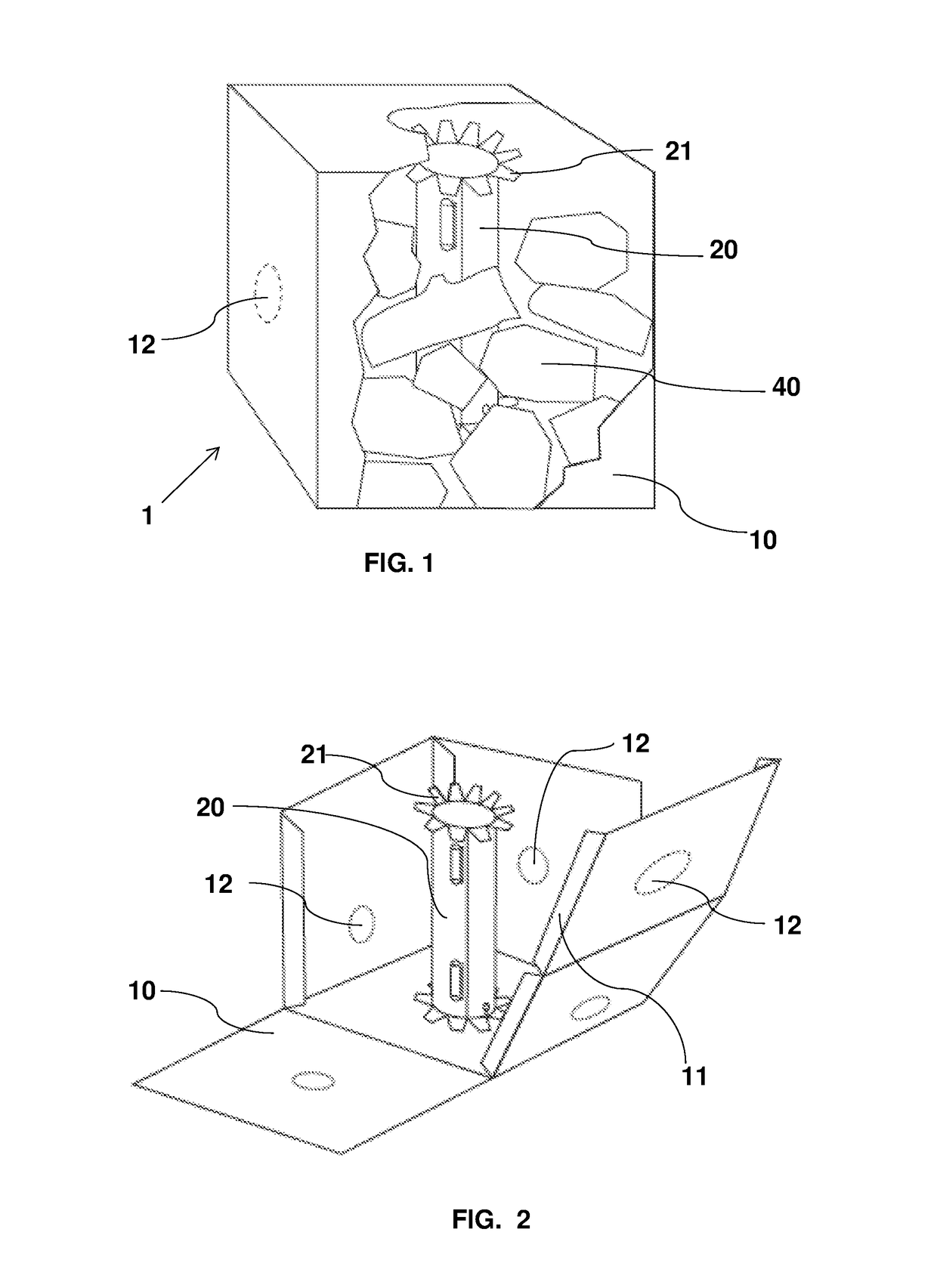
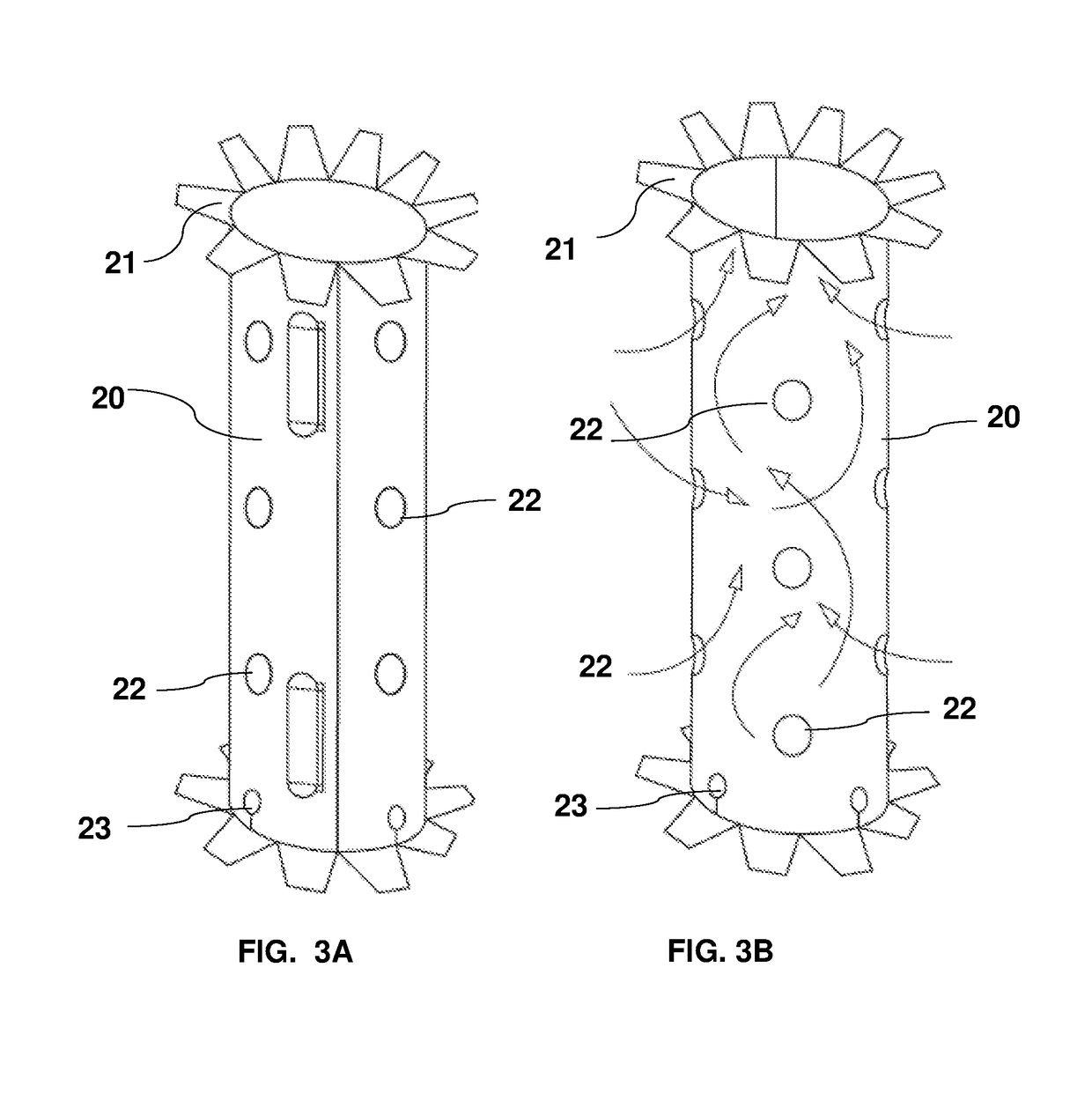
[0050]This invention relates to a fire start fuel container device (1) which keeps in its configuration a series of main elements for its correct operation, under normal operating conditions, said elements are a main container ...


PUM

PropertyMeasurementUnit
humidityaaaaaaaaaa
humidityaaaaaaaaaa
melting pointaaaaaaaaaa

Abstract

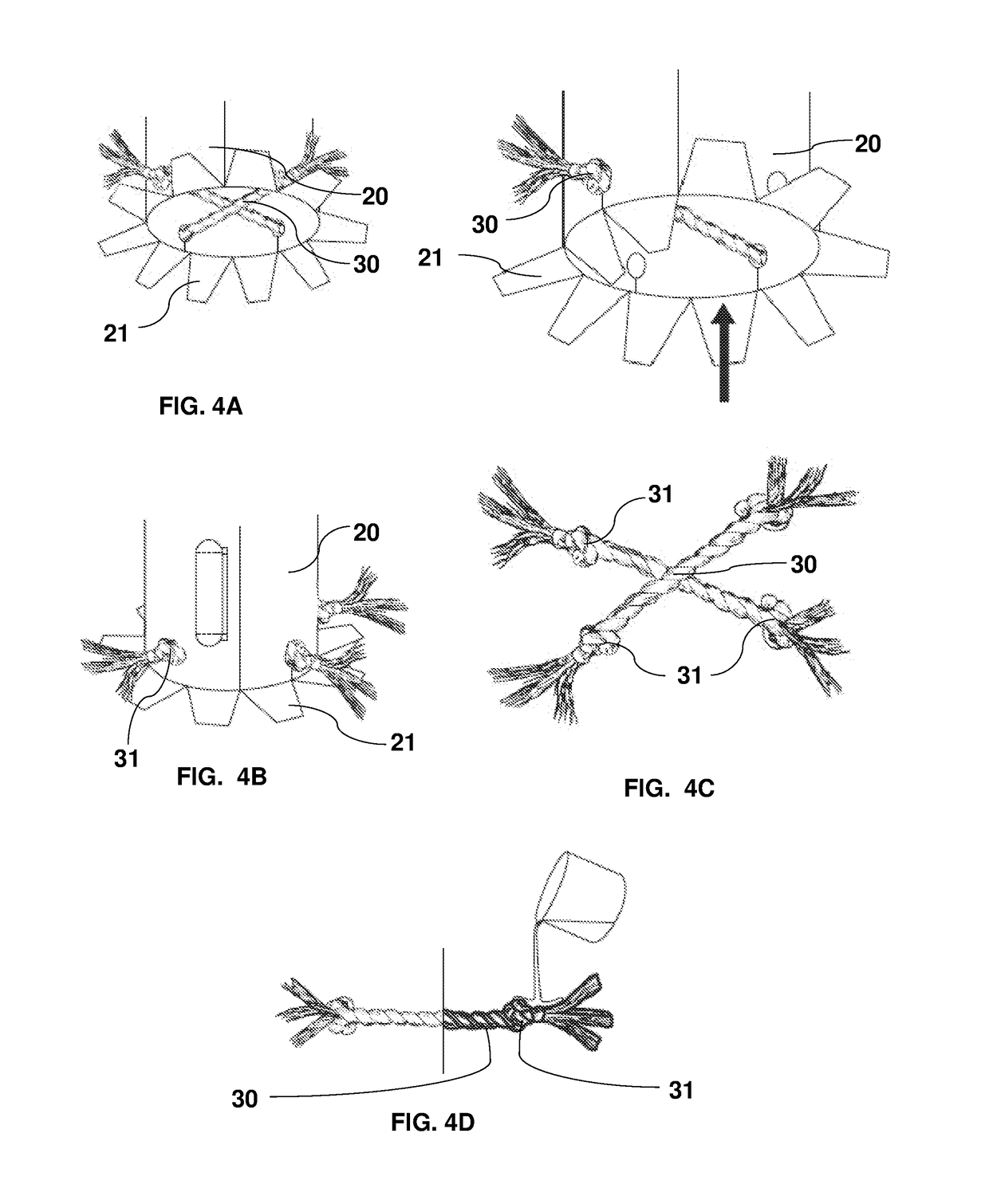
A fire start fuel container device including a container defined by side walls forming walls which contains a plurality of holes marked with suction, the holes arranged on at least one of the side faces with alternating arrangement in the central part and below the middle on an equatorial axis for each lateral face; and also has a face that forms the base and another face that makes the cover, which have a hole cut in the middle, which is larger diameter than the side holes, where all the faces define a space that it stores combustible material inside, including a fire initiating mechanism inside it, which is composed of a medium based on cellulose located in the central part of the container whose height reaches the entire height of the container, additionally the walls of the container. Fire initiating mechanism has a plurality of holes spaced equidistantly and arranged alternately one below or above the other on its entire surface, additionally has at its base two wax-coated wicks that cross each other and are fixed to the mechanism fire starter through four holes through which the ends of the wicks pass and by a stop preventing them from coming off, said stop made Referentially by a knot of the same wick.

Description

CROSS REFERENCE TO RELATED APPLICATION[0001]This application is a national stage entry of PCT / MX2016 / 000096 filed Sep. 27, 2016, under the International Convention claiming priority over Mexican Patent Application No. MX / a / 2016 / 002437 filed Feb. 23, 2016.TECHNICAL FIELD[0002]The present invention pertains to the field of kitchen equipment, particularly to the area of the equipment used in roasts or grilled and more specifically refers to a fire start fuel container deviceBACKGROUND OF THE INVENTION[0003]For many years the fuel industry has existed and prevailed, in different cultures and countries, as a means of ignition and heat generator to heat and cook foods that could only obtain a unique consistency and flavor from a cooking carried out through direct fire and embers.[0004]This industry from its origins and throughout all these years, has faced a great and constant challenge that to date has not been able to solve everything: the best combustion material and the best technique...

Claims


Application Information

Patent Timeline
Patent Type & Authority Applications(United States)
IPC IPC(8): A47J37/07C10L11/06C10L11/04
CPCA47J37/079C10L11/06C10L11/04C10L2230/06
Inventor VILLAREAL VIVES, JOSE ALEJANDROCARDENAS TORRES, RODRIGO
Owner VILLARREAL VIVES JOSE ALEJANDRO
Learn More