
Panel assembly

a panel and assembly technology, applied in sandwich construction, transportation and packaging, and spars/stringers, etc., can solve the problems of stringer run-out in aircraft wings composite skins, high shear and peel stress, stringer to peel off from the skin, etc., to avoid structural weakness and lightning strike problems, improve mechanical performance of reinforcement elements, and prevent leakage problems

Active Publication Date: 2019-02-14
AIRBUS OPERATIONS LTD
View PDF0 Cites 0 Cited by
  • Summary
  • Abstract
  • Description
  • Claims
  • Application Information

AI Technical Summary

Benefits of technology

The patent is about a new method of reinforcing structures using a polygonal curve made up of line segments connected by corners. This method allows the reinforcement elements to be more equally loaded by following the expected line of a curved crack front, thus avoiding failure of the reinforcement elements. The end row of reinforcement elements can have four, five, six, or more and can be bonded to the foot run-out and / or panel, which improves their mechanical performance and prevents leakage and structural weakness issues.

Problems solved by technology

The design of stringer run-outs in composite skins of aircraft wings presents a great technical challenge.
High shear and peel stresses can develop locally at the run-out causing the stringer to peel off from the skin.
Out of plane stresses develop at the tip of the run-out and since composites are poor in out-of-plane strength, cracks are prone to form at the tip.
Additionally, composites are poor in Mode-1 fracture toughness, so these cracks may grow.

Method used


Image

  • Panel assembly
  • Panel assembly
  • Panel assembly

Examples


Embodiment Construction

)

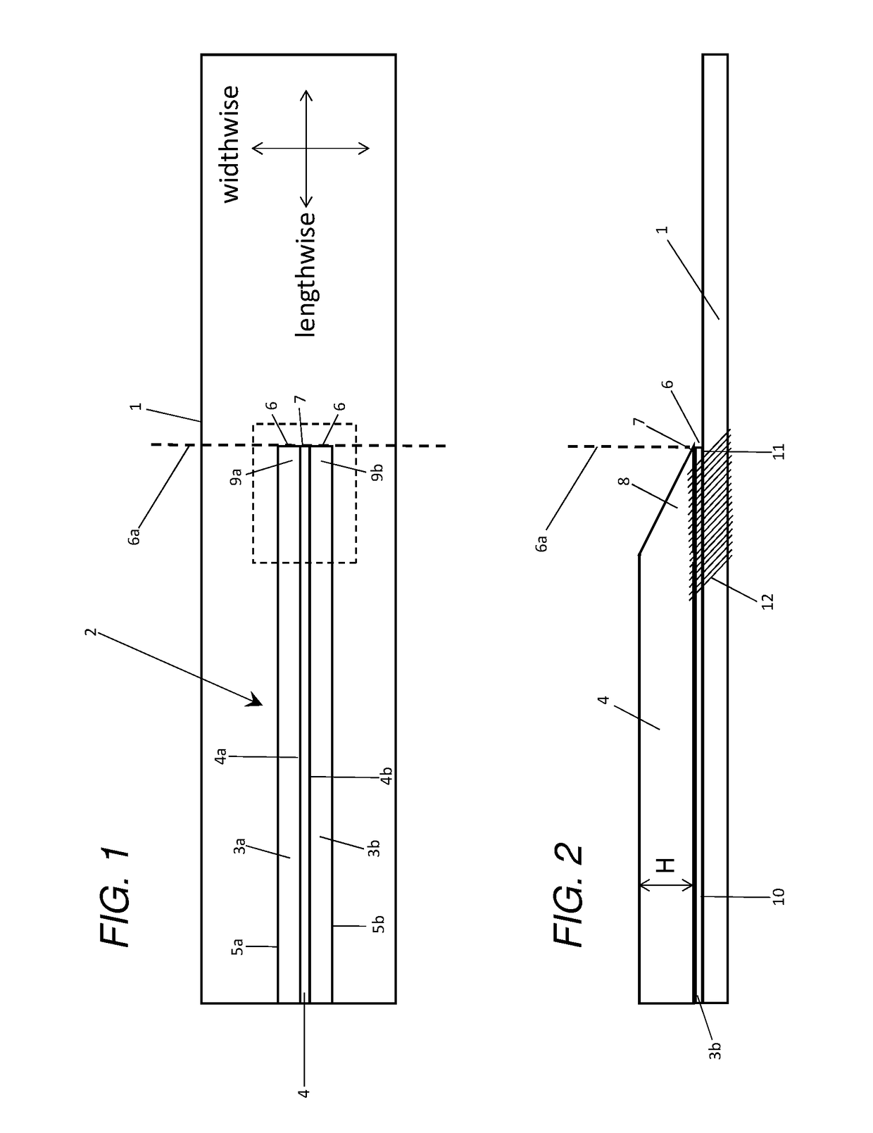
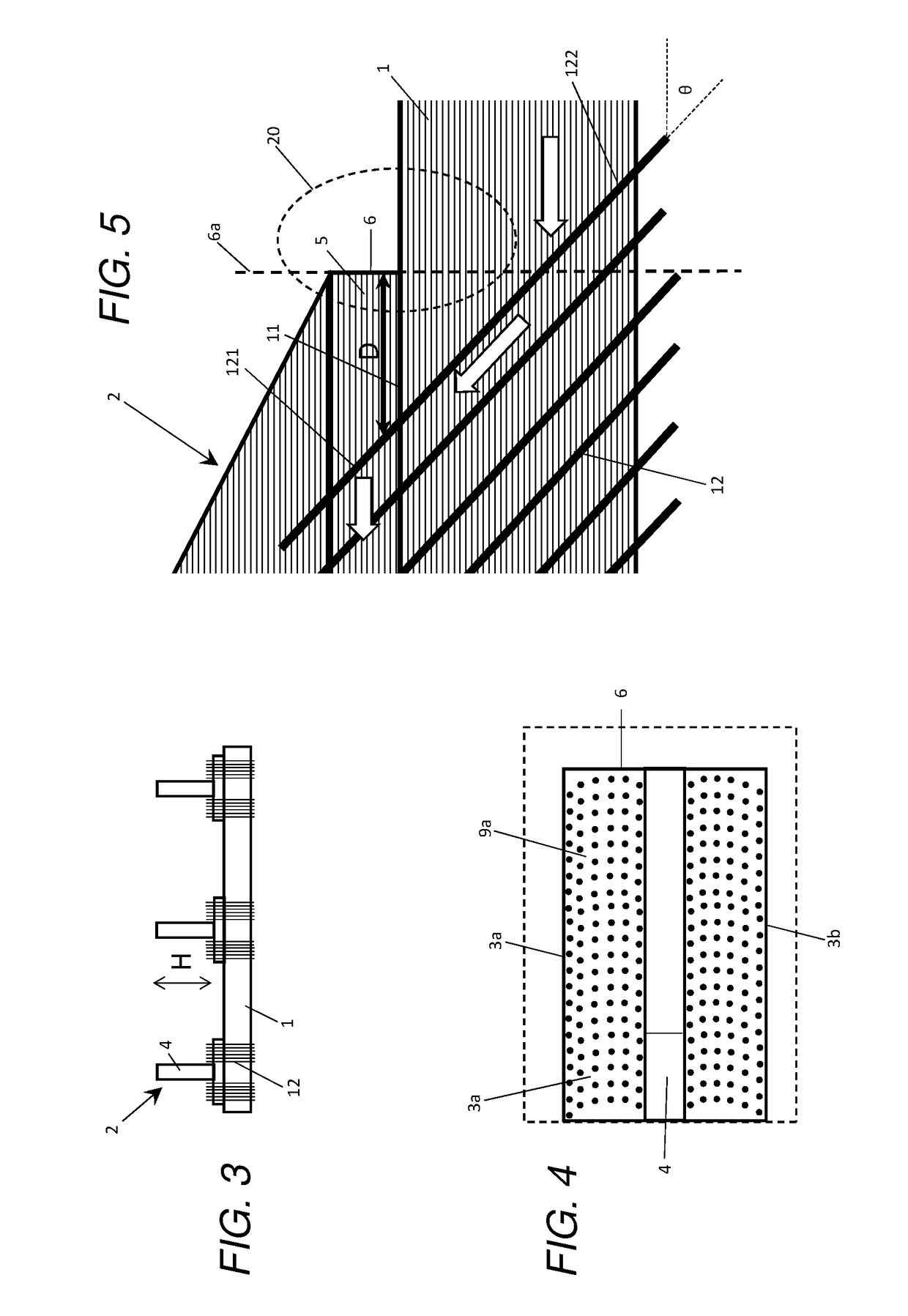
[0048]A panel assembly shown in FIGS. 1-5 comprises a panel 1 carrying multiple stringers 2. Only one of the stringers is shown in FIG. 1, but three of the stringers are shown side-by-side in FIG. 3. All of the stringers are similar, so only the stringer 2 shown in FIG. 1 will be described in detail.

[0049]The stringer 2 has a T-shaped cross-section as shown in FIG. 3, with a stringer foot and an upstanding stringer web 4. The stringer web 4 upstands by a maximum height H from the stringer foot as shown in FIGS. 2 and 3. At the end of the stringer web 4 there is a web run-out 8 which terminates at a tip 7. The web run-out 8 tapers so that the height of the web run-out 8 reduces towards the tip 7 as shown in FIG. 2.

[0050]The stringer foot has two symmetrical halves: a flange 3a and foot run-out part 9a on one side of the web; and a flange 3b and foot run-out part 9b on the other side of the web. The majority of the stringer foot comprises the flanges 3a,b which each extend in a width...


PUM

PropertyMeasurementUnit
Lengthaaaaaaaaaa
Fractionaaaaaaaaaa
Fractionaaaaaaaaaa

Abstract

A panel assembly with a panel and a stringer is disclosed. The stringer has a stringer foot and an upstanding stringer web. The stringer foot has a flange which extends in a widthwise direction between the stringer web and a lateral edge and in a lengthwise direction alongside the stringer web, and a foot run-out which extends between the flange and a tip of the stringer foot. The foot run-out is bonded to the panel at a foot run-out interface. Reinforcement elements, such as tufts, pass through the foot run-out interface into the panel. The reinforcement elements are distributed across the foot run-out interface in a series of rows including an end row nearest to the tip of the stringer foot and further rows spaced progressively further from the tip of the stringer foot. At least the end row has three or more of the reinforcement elements which are distributed along a polygonal curve.

Description

FIELD OF THE INVENTION[0001]The present invention relates to a panel assembly, typically but not exclusively for a composite skin of an aircraft wing.BACKGROUND OF THE INVENTION[0002]The design of stringer run-outs in composite skins of aircraft wings presents a great technical challenge. High shear and peel stresses can develop locally at the run-out causing the stringer to peel off from the skin. Out of plane stresses develop at the tip of the run-out and since composites are poor in out-of-plane strength, cracks are prone to form at the tip. Additionally, composites are poor in Mode-1 fracture toughness, so these cracks may grow.[0003]A known solution is to clamp the run-out to the skin with a metallic finger plate which is bolted to the stringer foot and skin, as disclosed in US2013 / 0313391.SUMMARY OF THE INVENTION[0004]A first aspect of the invention provides a panel assembly comprising: a panel; a stringer comprising a stringer foot and an upstanding stringer web, wherein the ...

Claims


Application Information

Patent Timeline
IPC IPC(8): B64C3/18B64C3/26B64C1/12B64C1/06
CPCB64C3/182B64C3/26B64C1/12B64C1/064B64C2001/0072B29C70/00B64C3/20Y02T50/40B29C66/71B29K2063/00
Inventor JAISWAL, VIMALWOOLCOCK, JOHN
Owner AIRBUS OPERATIONS LTD
Learn More