
Hydraulic control device

a control device and hydraulic technology, applied in the direction of gearing control, gearing elements, servomotors, etc., can solve the problems of fuel efficiency deterioration, excessive amount of generated power, and loss of workload, so as to reduce the workload of the engine, reduce the driving torque of the first pump, and reduce the pressure of the first oil

Active Publication Date: 2019-02-14
HONDA MOTOR CO LTD
View PDF0 Cites 11 Cited by
  • Summary
  • Abstract
  • Description
  • Claims
  • Application Information

AI Technical Summary

Benefits of technology

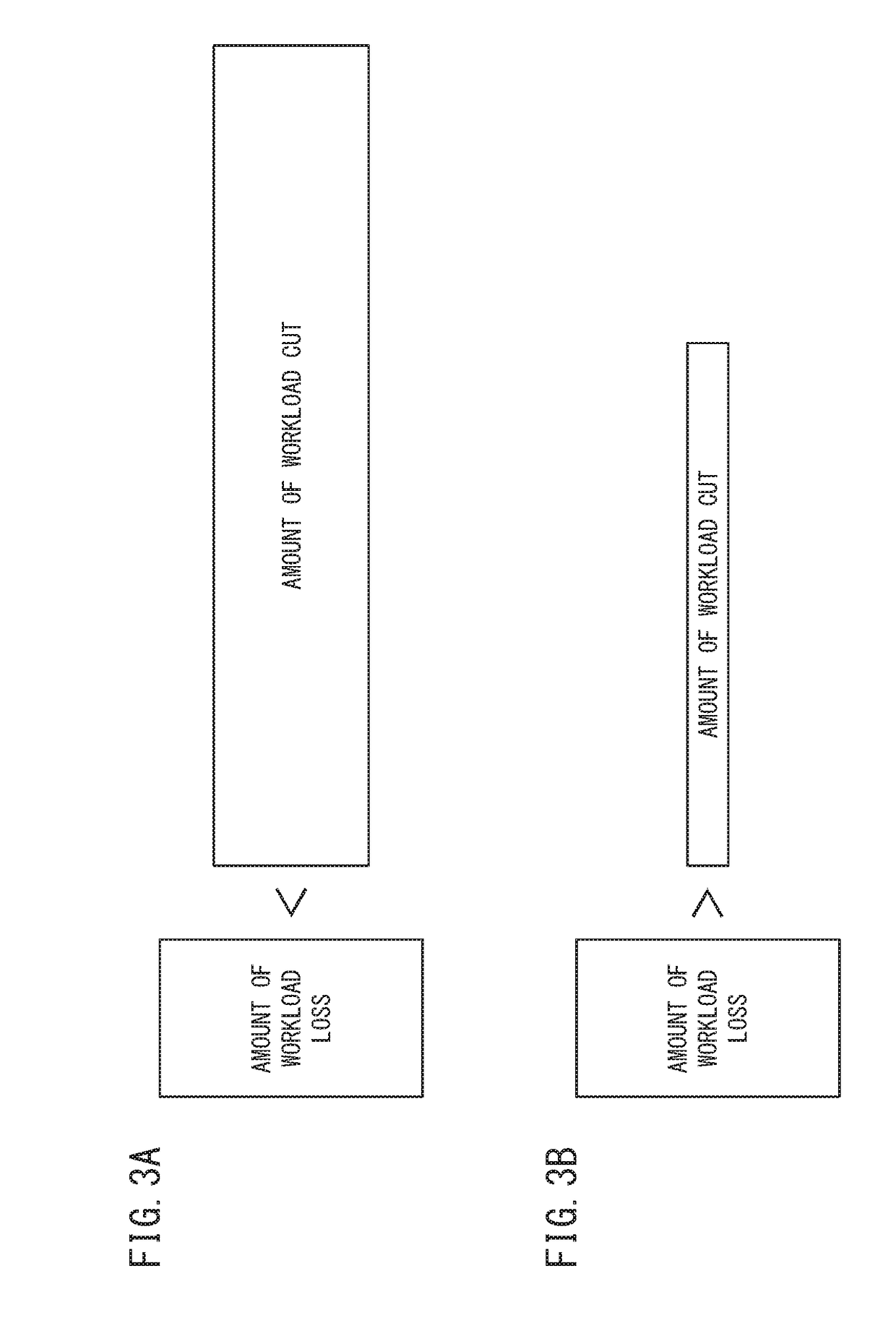
The present invention is an improvement of a hydraulic control device for vehicles. The invention aims to supply oil to a hydraulic operation unit efficiently without deteriorating fuel efficiency. The device includes a first pump and a second pump, which work together to control the pressure of the oil. When the second pump is started, the driving torque of the first pump is reduced so as to reduce the pressure of the oil. This reduces the workload of the engine and makes it more efficient. The device also includes a workload calculation unit and a workload determination unit to accurately determine the workload of the first and second pumps. By setting a threshold, the workload determination unit can perform the determination process accurately. Even if the amount of workload loss is less than or equal to the amount of workload cut, the motor controller may be configured to stop the motor or decrease the rotation number of the motor when fuel cut for the engine is performed. This prevents the driving of the second pump from canceling out the improvement of fuel efficiency.

Problems solved by technology

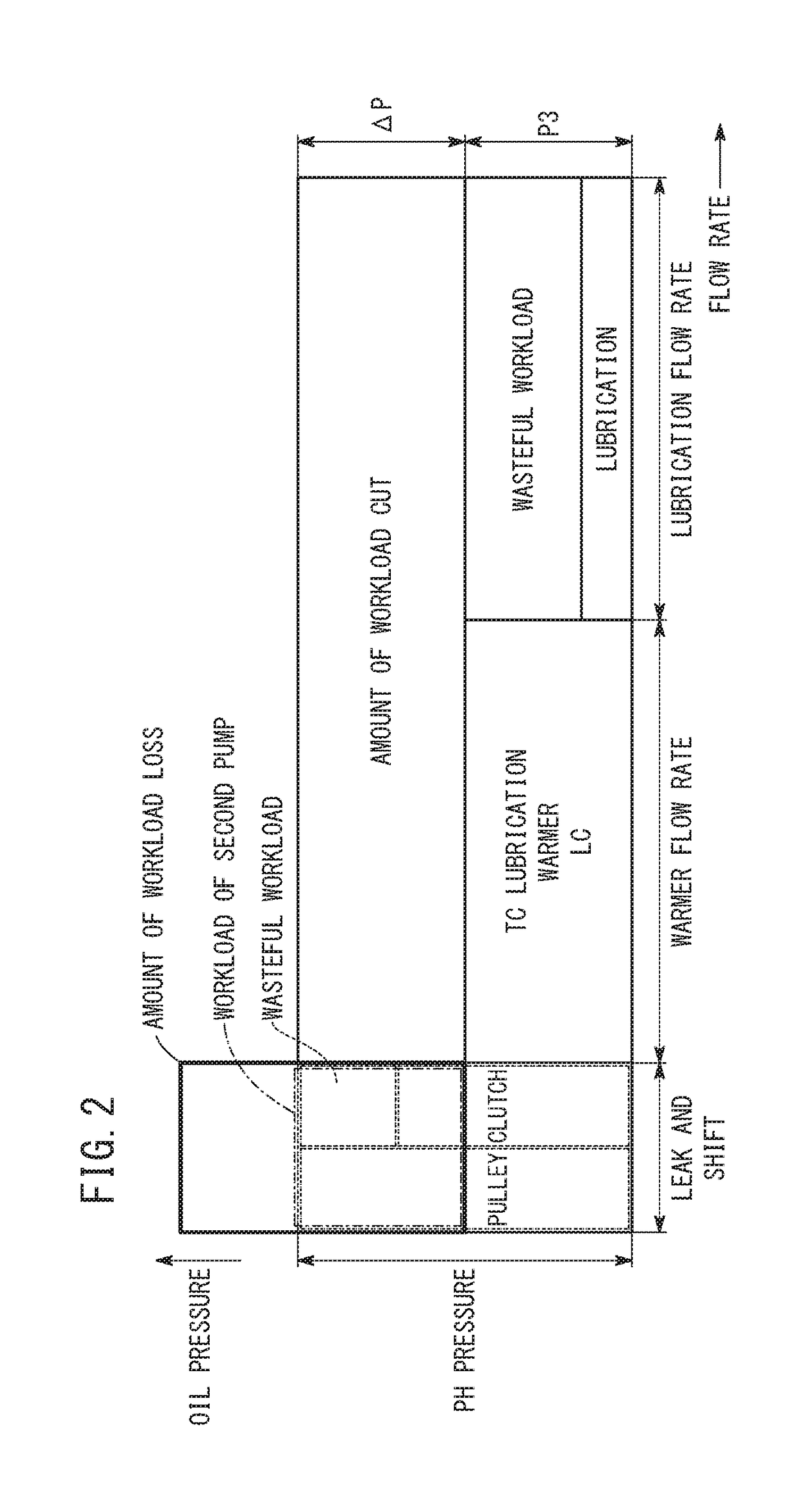
Therefore, the excessive amount of generated power corresponds to an amount of workload loss in regard to the supply of the second oil from the second pump to the hydraulic operation unit.
As a result, even if the workload of the first pump is reduced by driving the second pump in order to improve the fuel efficiency of the vehicle, the fuel efficiency may rather deteriorate depending on the balance between the workload that is cut in the first pump (the amount of workload cut) and the amount of workload loss.

Method used


Image

  • Hydraulic control device
  • Hydraulic control device
  • Hydraulic control device

Examples


Embodiment Construction

[0023]A preferred embodiment of a hydraulic control device according to the present invention will hereinafter be described in detail with reference to the attached drawings.

1. Structure of the Present Embodiment

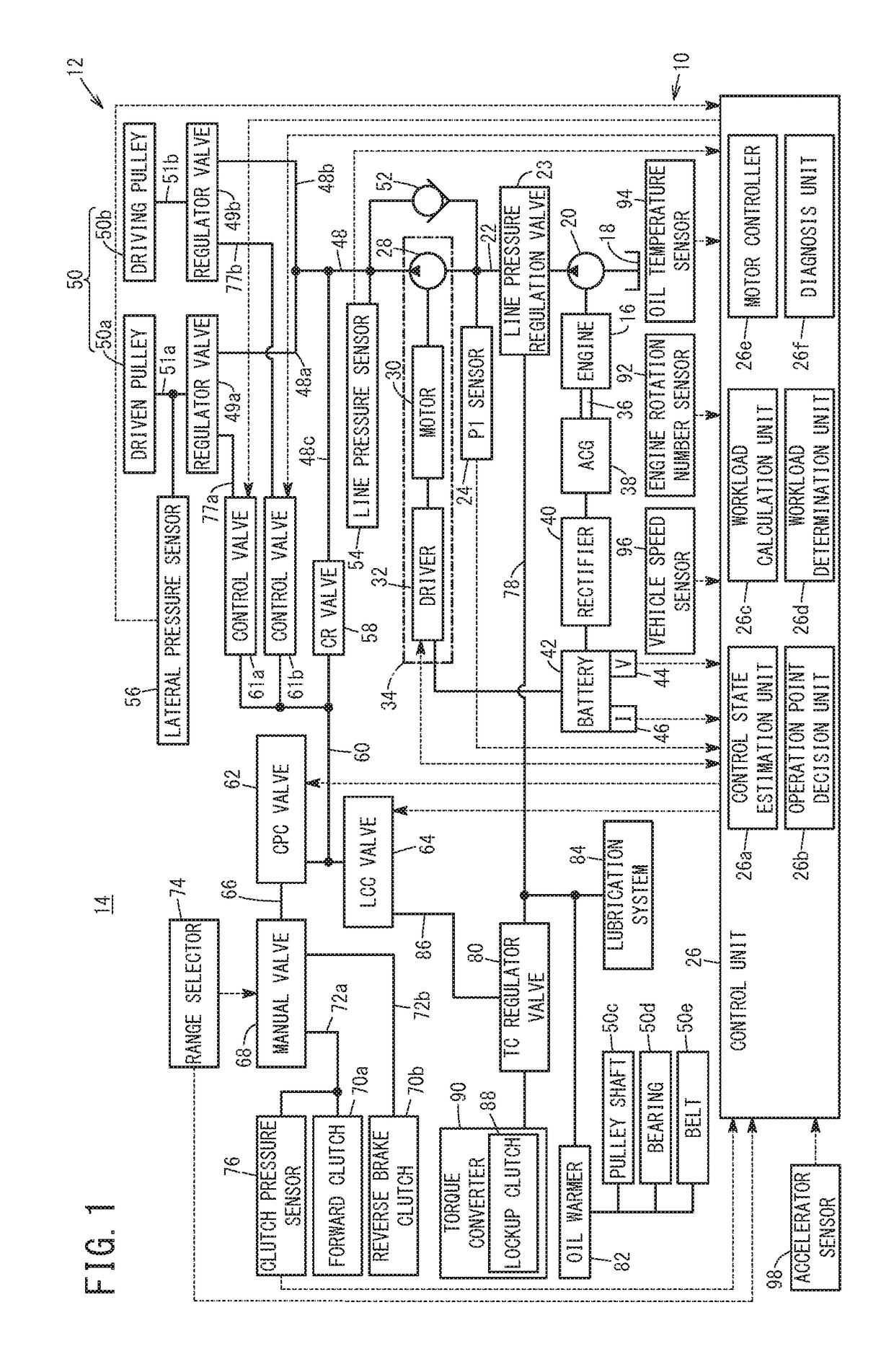
[0024]FIG. 1 is a structure diagram of a hydraulic control device 10 according to the present embodiment. The hydraulic control device 10 is used in, for example, a vehicle 14 including a transmission 12 corresponding to a continuously variable transmission (CVT).

[0025]The hydraulic control device 10 includes a first pump (mechanical pump) 20 that is driven by an engine 16 of the vehicle 14 and pumps up oil (hydraulic oil) stored in a reservoir 18 and transfers the oil with pressure. An output side of the first pump 20 is connected to an oil passage 22. The oil that is transferred with pressure from the first pump 20 flows as first oil in the oil passage 22. In the middle of the oil passage 22, a line pressure regulation valve 23 corresponding to a spool valve is provided.

[0...


PUM


Abstract

In a control unit of a hydraulic control device, a workload calculation unit calculates the amount of workload cut in a first pump when supply of first oil from the first pump to a continuously variable transmission mechanism through a check valve is switched to supply of second oil from a second pump to the continuously variable transmission mechanism. A workload determination unit determines whether the amount of workload loss of an ACG is more than the amount of workload cut. A motor controller stops a motor or decreases a rotation number if the workload determination unit determines that the amount of workload loss is more than the amount of workload cut.

Description

CROSS-REFERENCE TO RELATED APPLICATION[0001]This application is based upon and claims the benefit of priority from Japanese Patent Application No. 2017-155235 filed on Aug. 10, 2017, the contents of which are incorporated herein by reference.BACKGROUND OF THE INVENTIONField of the Invention[0002]The present invention relates to a hydraulic control device that has, between a first pump and a hydraulic operation unit, a second pump and a check valve connected in parallel, and that supplies first oil from the first pump to the hydraulic operation unit through the check valve, or pressurizes the first oil with the second pump and supplies the first oil that has been pressurized to the hydraulic operation unit as second oil.Description of the Related Art[0003]For example, Japanese Laid-Open Patent Publication No. 2015-200369 discloses a hydraulic control device in a transmission of a vehicle that has, between a first pump (mechanical pump) and a hydraulic operation unit of the transmissi...

Claims


Application Information

Patent Timeline
IPC IPC(8): F15B11/16F16H61/00F15B11/17
CPCF15B11/165F16H61/0031F15B11/17F15B2211/20576F15B2211/20515F15B2211/20523F15B2211/2658F15B2211/6343F15B2211/633F15B2211/6651F16H59/44F16H59/52F16H59/72F16H2059/746F16H59/74F16H61/02F16H61/662F16H61/664F16H61/0267
Inventor HARADA, MASAMICHI
Owner HONDA MOTOR CO LTD
Learn More