

Lighting device
a lighting device and grid-shaped technology, applied in lighting and heating apparatus, electric lighting, light source combinations, etc., can solve the problems of undesired spottiness and/or inhomogeneous illumination, the overall efficiency of the known grid-shaped lighting device is relatively low, and the suitable use of the known lighting device is limited to a relatively small number of applications. , to achieve the effect of improving the homogeneity of observed illumination and increasing the opening siz
- Summary
- Abstract
- Description
- Claims
- Application Information
AI Technical Summary
Benefits of technology
Problems solved by technology
Method used
Image

Examples
first embodiment
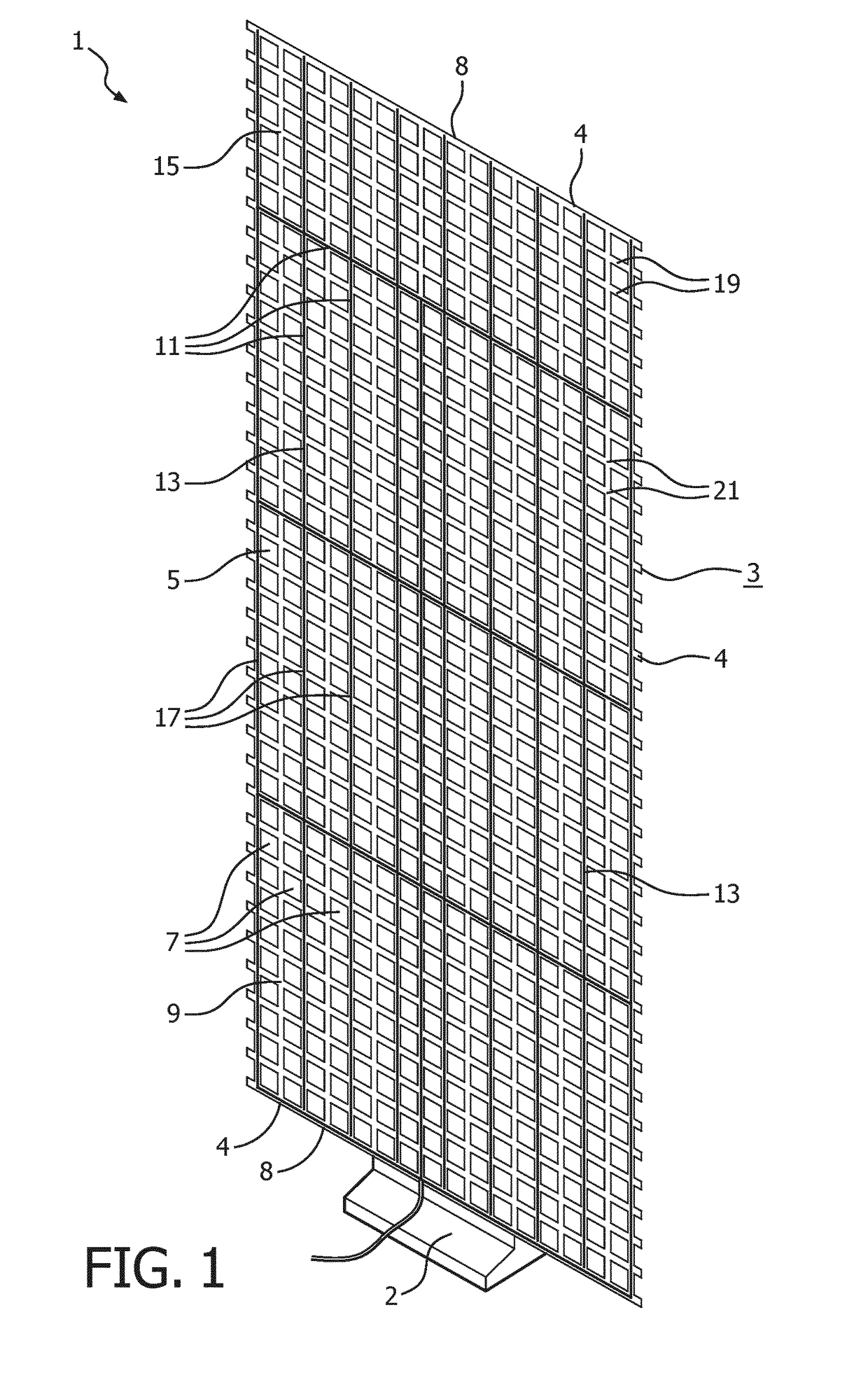
[0039]FIG. 1 shows a prototype of the lighting device 1 according to the invention illustrating the principle structure of the lighting device. The lighting device comprises a grid sheet carrier 3 having a border 4 having two opposite side edges 8. The grid sheet carrier comprising an open surface area 5 which is the sum of a plurality of openings 7 and comprising carrier material 9 surrounding each of said openings with a respective perimeter 10 of grid sheet carrier material, said carrier material being arranged in a two-dimensional, first pattern 11 which is similar to the shape of a trellis. The grid sheet carrier is mounted via a part of its side edges 8 of border 4 on a base part 2. A plurality of LEDs 13 mounted on both bridges 19 and nodes 21 on only a first main face 15 of the carrier material and arranged in a two-dimensional, second pattern 17 of parallel lines. The LEDs arranged to aim light toward a reflective surface during operation such that a majority of said light ...
second embodiment
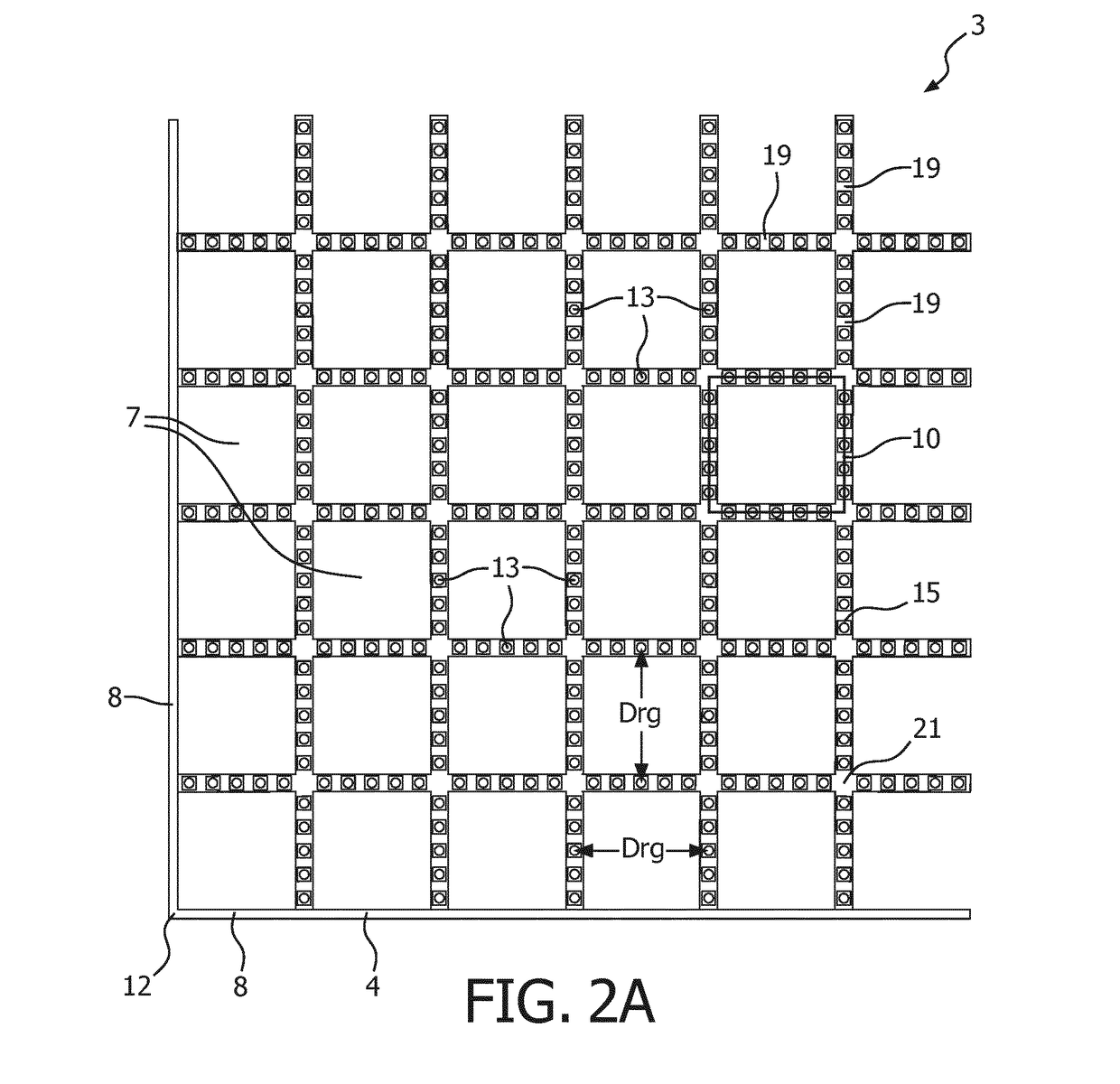
[0040]FIG. 2A shows a portion of a grid sheet carrier 3 according to the invention to be mounted via a corner 12 formed by side edges 8 of its border 4 on a base part (not shown) with FIG. 2B showing a detail of said grid sheet. The grid sheet carrier comprises a plurality of square shaped openings 7 and a plurality of LEDs 13 mounted on one, i.e. the first, main face 15 of the grid sheet carrier. The LEDs are mounted as a row of five LEDs on each side of the perimeter 10 of each opening, i.e. only at bridges 19 between the openings and not at nodes 21. Hence, the number of associated LEDs per opening is twenty and the ratio R between the number of LEDs and openings is ten, as each row of five LEDs is shared between two adjacent openings. The shortest distance between LEDs of opposite sides is the same as the average distance Drg between LEDs on opposite sides around one opening.
[0041]In this embodiment the LEDs are individually addressable. Thereto, a grid like pc board 23 covered ...
third embodiment
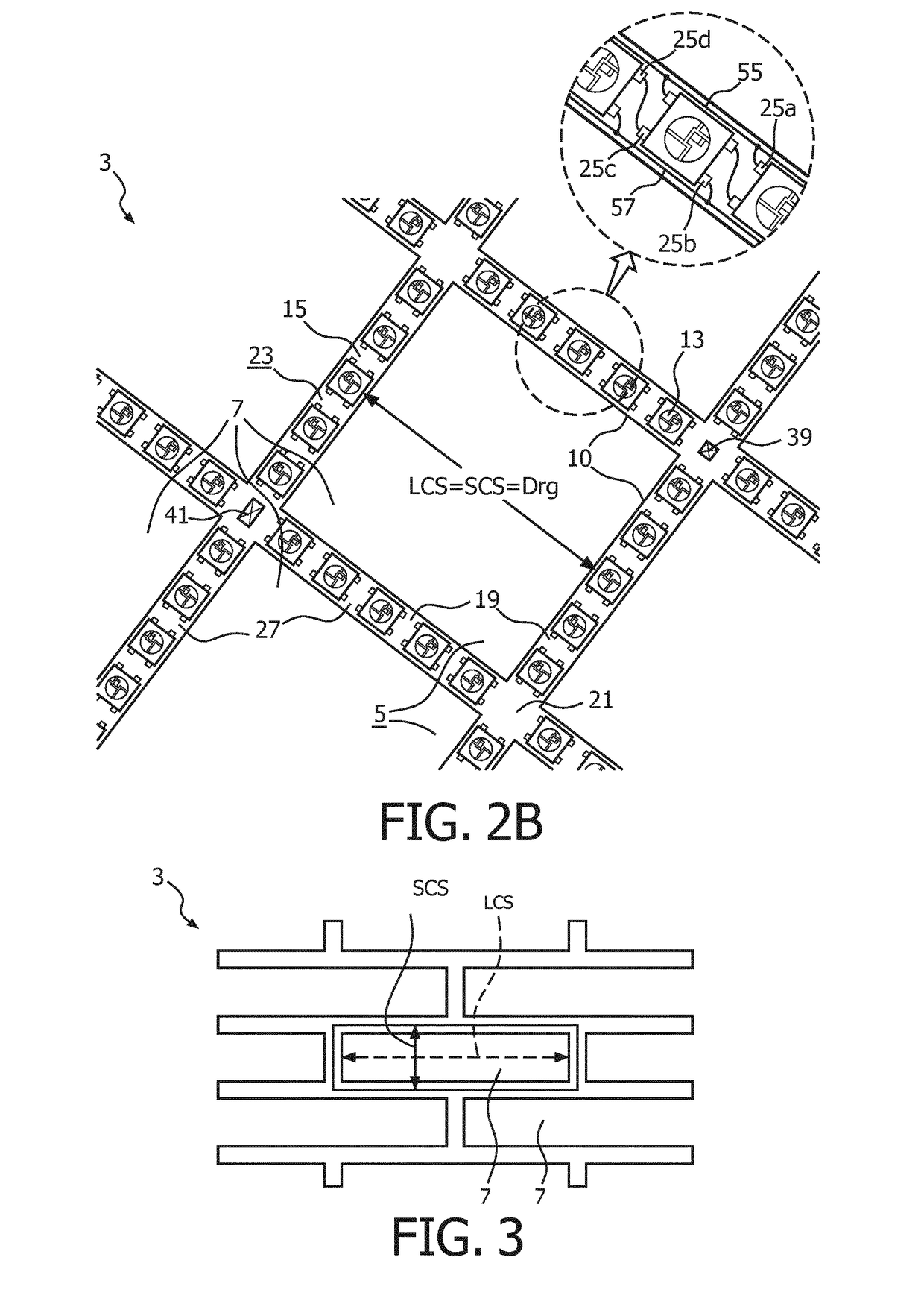
[0042]FIG. 3 shows a part of a grid sheet carrier 3 according to the invention in which the grid sheet carrier has a ratio CSr between the largest LCS and smallest cross section SCS of each opening 7 of about four, i.e. well within the ratio of 1<CSr<=6. Note that if the shape of the openings is very elongated, i.e. has large difference in opposite LED distances, as is the case in FIG. 3, the most prevalent distance, or the average distance between opposite LEDs preferably should be used as a base for the estimation of Drg, see also FIG. 2B and FIG. 4-A-C. In the case of the FIG. 3 this is SCS, since more opposite LED pairs are at this shorter distance.
[0043]FIG. 4A-C shows three illustrative examples of (dynamic) light patterns 29 obtained by the lighting device 1 according to the invention in an installed, operating state. The lighting device has regular grid 3 mounted with a part of its border 4 on a base part 2 and on which grid the LEDs (not shown / visible) are mounted and which...
PUM
 Abstract
Description
Claims
Application Information