Eureka AIR delivers breakthrough ideas for toughest innovation challenges, trusted by R&D personnel around the world.

Turbo receivers for single-input single-output underwater acoustic communications

a receiver and underwater acoustic technology, applied in the field of underwater acoustic communication receivers, can solve the problems of echoes and signal interference, difficult selection of modulation and error correction techniques, so as to improve the robustness and performance of the receiver, improve the uwa communication system, and increase reliability

Inactive Publication Date: 2019-02-21
UNIVERSITY OF MISSOURI
View PDF20 Cites 15 Cited by
  • Summary
  • Abstract
  • Description
  • Claims
  • Application Information

AI Technical Summary

Benefits of technology

This patent is about improving underwater communication systems by using turbo equalization of SISO UWA transmissions. The turbo equalization may be performed by a receiver using various methods such as Bi-SDFE or CE MMSO-TEQs and Direct-Ad Ada-TEQs. The use of time-reversed SDFE and linear combining scheme may enhance the performance of the receiver by achieving better robustness and performance. The estimated covariance matrix and mean vector of the outputs are then used for adaptation of the SDFE filter coefficients in a next iteration of turbo equalization. The patent aims to increase reliability, reduce complexity, size, and cost, and make such systems more robust under harsh channel conditions as well as the expected challenges present in an underwater environment.

Problems solved by technology

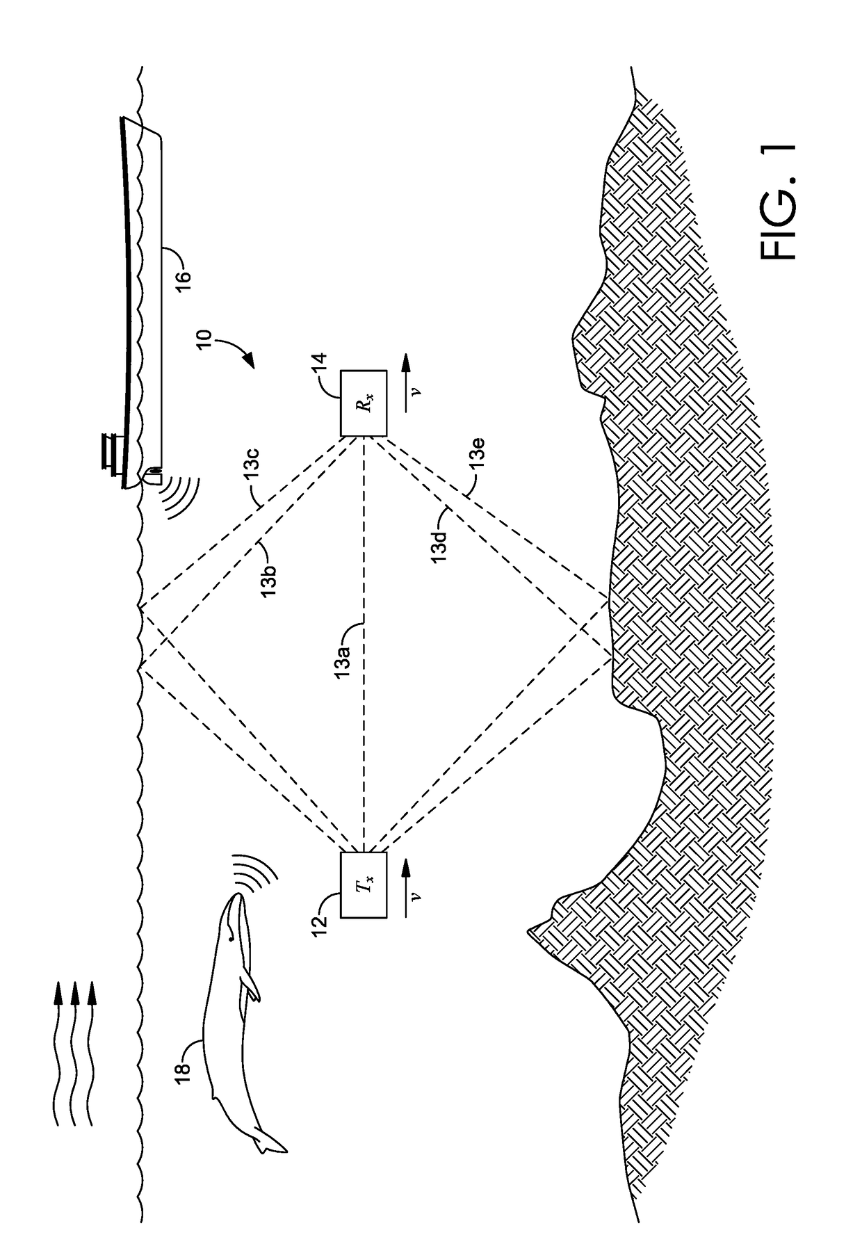
However, the underwater acoustic (“UWA”) channel presents many unique challenges for the design of underwater communication systems.
Some of these challenges include time-varying multipath signals due to reflections off the moving surface waves and rough ocean bottom, which can cause echoes and signal interference.
In addition, noise is introduced by wind, shipping traffic, and various forms of ocean life, which can mask a portion of the signal and block the corresponding carried data.
These challenges can cause the UWA signal to fluctuate randomly and as a result make the selection of modulation and error correction techniques very challenging.

Method used


Image

  • Turbo receivers for single-input single-output underwater acoustic communications
  • Turbo receivers for single-input single-output underwater acoustic communications
  • Turbo receivers for single-input single-output underwater acoustic communications

Examples


second embodiment

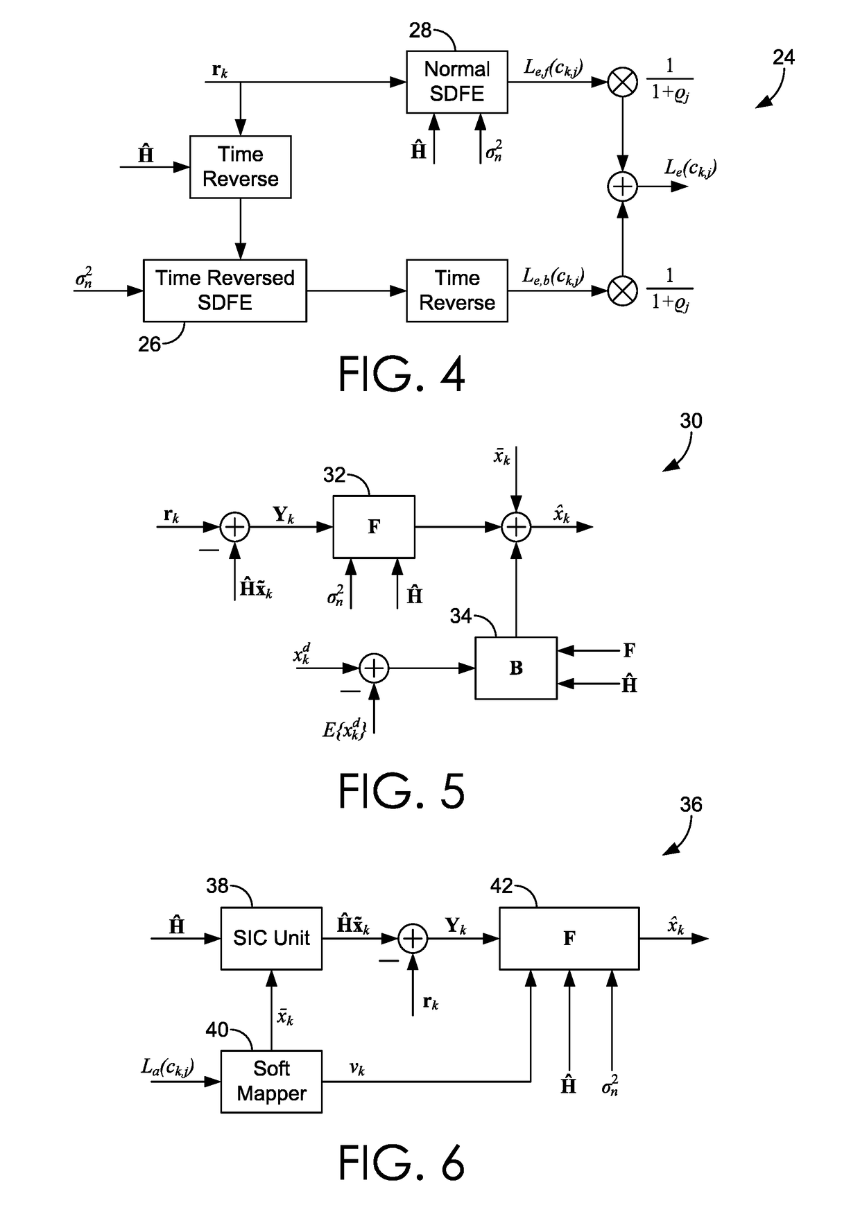
[0045]In a second embodiment, the turbo equalizer 20 may comprise a CE-based SDFE. For example, the CE-based SDFE may comprise the exemplary SDFE 30 discussed above in reference to FIG. 5. An estimated symbol {circumflex over (x)}k may be determined by equation (6) where F is the feedforward filter, B is the feedback filter of length K3=K2+L−1, and dk is the time-varying offset. The input vector of the feedback filter is defined by equation (7) where xkd is the a posteriori soft decision estimated by combining the a priori LLRs La (ck,j) and bit extrinsic LLRs Le(ck,j). The filters in the exemplary SDFE 30 at each turbo iteration are determined by equations (8a)-(8c) below, where Cff, Cfb and Cbb are the covariance matrices.

FH=[σw2IK+Ĥ(Cff−Cfb(Cbb)−1CfbH)ĤH]−1  (8a)

BH=−(Cbb)−1ĤCfbHFH  (8b)

dk=E{xk}−FĤE{xk}−BE{xkd}  (8c)

The covariance matrices Cff, Cfb, and Cbb are defined by equations (9a)-(9c) below.

Cff=E{xkxkH}−E{xk}E{xkH}  (9a)

Cfb=E{xkxkdH}−E{xk}E{xkdH}  (9b)

Cbb=E{xkdxkdH}−E{xd}E{...

third embodiment

[0046]In a third embodiment, the turbo equalizer 20 may comprise a CE-based LMMSE turbo equalizer that estimates the transmitted symbol {circumflex over (x)}k using the received signal rk and the a priori LLRs La (ck,j) provided by the MAP decoder 22. Turning to FIG. 6, with continuing reference to FIG. 3, a block diagram of an exemplary CE-based LMMSE turbo equalizer 36 is depicted. The exemplary CE-based LMMSE turbo equalizer 36 includes a serial interference cancellation (“SIC”) unit 38, a soft mapper 40, and a feedforward filter 42. The a priori information La (ck,j) is provided to the soft mapper 40, which uses the a priori LLRs La(ck,j) to compute an a priori soft decision 4. The a priori soft decision may be determined by equations (10) and (11) below.

x_k=E[xk|{La(ck,j)}j=1Q]=∑αi∈SαiP(xk=αi)where(10)P(xk=αi)=∏j=1q12(1+s~i,jtanh(La(ck,j) / 2))ands~i,j={+1ifsi,j=0-1ifsi,j=1.(11)

The a priori soft decision xk is fed into the SIC unit 38 along with an estimated channel Ĥ and a recon...

fourth embodiment

[0048]In a fourth embodiment, the turbo equalizer 20 may comprise a Soft DA-TEQ that estimates the transmitted symbol {circumflex over (x)}k using the received signal rk and the a priori soft decisions La(ck,j) provided by the MAP decoder 22. Turning now to FIG. 7, a block diagram of a turbo receiver having an exemplary Soft DA-TEQ 44 is depicted. The exemplary Soft DA-TEQ includes a feedforward filter 46 and a soft interference cancellation filter 48. The estimated transmitted symbol {circumflex over (x)}k may be determined with equation (14) below, where Fk is the feedforward filter and Bk is the soft interference cancellation filter.

{circumflex over (x)}k=FkHrk+BkH{tilde over (x)}k  (14)

[0049]Equation (13) can be reformulated as {circumflex over (x)}k=GkHUk, where Gk=[FkT BkT]T is the concatenation of the feedforward and soft interference filters, and Uk=[rkT {tilde over (x)}kT]T is the overall input of said filters. The equalizer coefficients may be directly estimated by the DA-...


PUM


Abstract

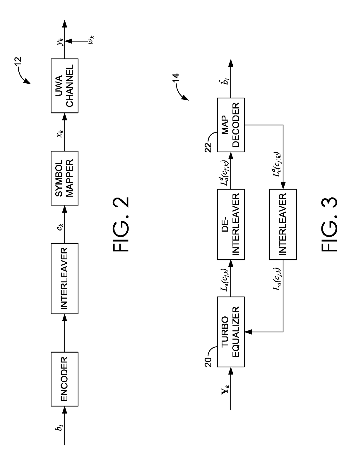
Systems and methods for underwater communication using a SISO acoustic channel. An acoustic receiver may receive a signal comprising information encoded in at least one transmitted symbol. Using a Bi-SDFE, the at least one transmitted symbol is estimated. The Bi-SDFE may include a SDFE and a time-reversed SDFE that each output bit extrinsic LLRs, which are combined into combined bit extrinsic LLRs. The estimated symbol is then mapped to the combined bit extrinsic LLRs, the result of which is de-interleaved. Iterative bit extrinsic LLRs are generated with a MAP and / or soft-decision decoder using the mapped, combined bit extrinsic LLRs as a priori LLRs for the Bi-SDFE in another iterative estimation. The iterative bit extrinsic LLRs are interleaved and transmitted for use by the Bi-SDFE in another iterative estimation. After a plurality of iterations, a hard decision of the transmitted symbol is generated with the MAP and / or soft-decision decoder.

Description

CROSS-REFERENCE TO RELATED APPLICATIONS[0001]This application, having attorney docket number 17MST015 / UNOM.271561 and entitled “Improved Turbo Receivers for Single-Input Single-Output Underwater Acoustic Communications,” claims priority to U.S. Provisional Application 62 / 483,358, filed Apr. 8, 2017, entitled “Improved Turbo Receivers for Single-Input Single-Output Underwater Acoustic Communications.” The entirety of the aforementioned application is incorporated by reference herein.STATEMENT REGARDING FEDERALLY SPONSORED RESEARCH OR DEVELOPMENT[0002]This invention was made with U.S. Government support by way of Grant Numbers ECCS-0846486 and ECCS-1408316 awarded by the National Science Foundation and Grant Number N00014-10-1-0174 awarded by the Office of Naval Research. The Government has certain rights in the invention. See 35 U.S.C. § 202(c)(6).FIELD[0003]The present invention relates generally to improved systems and methods for performing equalization and decoding of single-inpu...

Claims


Application Information

Patent Timeline
Patent Type & Authority Applications(United States)
IPC IPC(8): H04B13/02H04L1/00H04L25/03H04B11/00
CPCH04B13/02H04L1/0055H04L25/03171H04L25/03057H04B11/00H04L2025/0342H04L2025/03401H04L2025/03636H04L2025/03426
Inventor ZHENG, YAHONG ROSADUAN, WEIMINXIAO, CHENGSHAN
Owner UNIVERSITY OF MISSOURI
Why Eureka
Eureka Blog
Learn More