Percutaneous bone graft delivery system and method

a bone graft and percutaneous technology, applied in the field of percutaneous bone graft delivery system and method, can solve the problems of cumbersome procedure, difficulty in delivering such bone graft materials percutaneously during minimally invasive surgical procedures,

Active Publication Date: 2019-02-28
STRYKER EURO OPERATIONS HLDG LLC
View PDF0 Cites 9 Cited by
  • Summary
  • Abstract
  • Description
  • Claims
  • Application Information

AI Technical Summary

Problems solved by technology

However, there are challenges to delivering such bone graft materials percutaneously during minimally invasive surgical procedures.
This results in a cumbersome procedure in which an access portal fixed to the OR table may need to be positioned as desired, and then the surgeon uses both hands to operate the graft delivery system.

Method used


Image

  • Percutaneous bone graft delivery system and method
  • Percutaneous bone graft delivery system and method
  • Percutaneous bone graft delivery system and method

Examples


Embodiment Construction

[0072]As used herein, the term “proximal” refers to a location closer to a surgeon or other personnel using the device as described herein, while the term “distal” refers to a location farther away from the surgeon using the device.

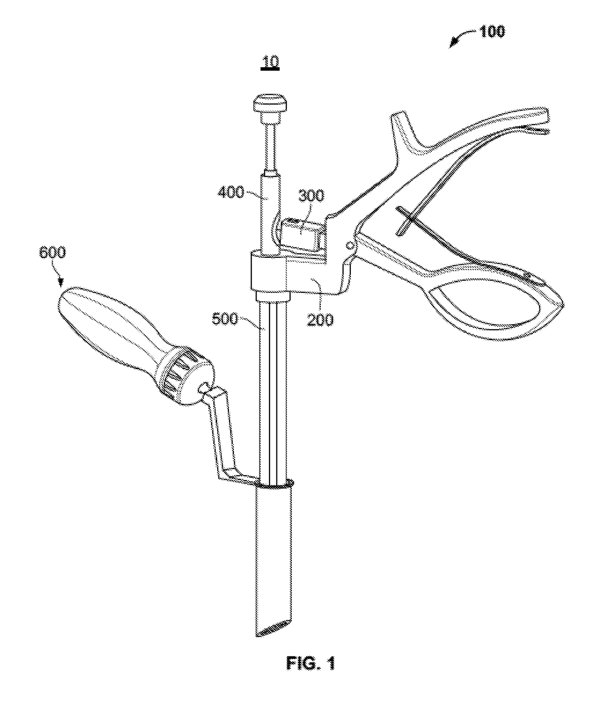
[0073]A bone graft delivery system 10 is illustrated in FIG. 1 according to an embodiment of the disclosure. Generally, system 10 comprises an injector assembly 100 and an access portal assembly 600.

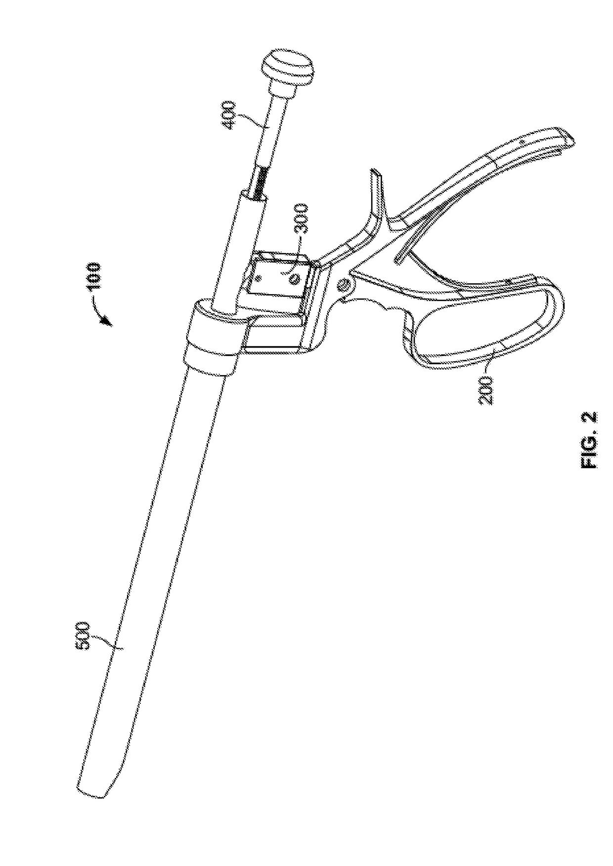
[0074]Injector assembly 100, illustrated alone in FIG. 2, may include a number of subassemblies including, for example, a handle subassembly 200, a ratchet subassembly 300, a plunger subassembly 400, and a delivery tube subassembly 500. Handle subassembly 200 may be used to advance plunger subassembly 400 in an incremental or continuous fashion through delivery tube subassembly 500 to force a material out of a distal end thereof. For embodiments with incremental advancement of plunger subassembly 400, handle subassembly 200 and the plunger subassembly may work...


PUM


Abstract

A bone graft delivery system includes a bone graft injector and an access portal. The access portal may include a handle having a first arm pivotably connected to, and biased away from, a second arm. A ratchet including a pawl may extend from the second arm. A delivery tube may be configured to mate with the first arm and be configured to store a bone graft material therein. A plunger including a shaft and a plunger tip at the distal end thereof may be configured to move through the delivery tube. At least a portion of the shaft may include teeth, the pawl of the ratchet being configured to iteratively contact the teeth. A user may hold the access portal with a first hand and the bone graft injector with a second hand, iteratively squeezing the handle to iteratively eject amounts of bone graft material into a patient.

Description

CROSS-REFERENCE TO RELATED APPLICATIONS[0001]The present application is a continuation of U.S. patent application Ser. No. 14 / 520,607, filed Oct. 22, 2014, which claims the benefit of the filing date of U.S. Provisional Patent Application No. 61 / 894,549 filed Oct. 23, 2013, the disclosures of which are hereby incorporated by reference herein.FIELD OF THE INVENTION[0002]The present invention relates to apparatus and methods for delivering materials to bone during a surgical procedure, and more particularly to injectors and access portals for percutaneously delivering bone graft or bone graft substitute material during spinal procedures.BACKGROUND[0003]There is an increasing prevalence in spinal procedures being performed percutaneously in a minimally invasive way. Often, spinal fixation procedures include delivery of bone graft or bone graft substitute to aid implants or screws in fixing and / or fusing portions of the spinal column. However, there are challenges to delivering such bon...

Claims


Application Information

Patent Timeline
Patent Type & Authority Applications(United States)
IPC IPC(8): A61F2/46A61B17/02A61B17/34A61B17/70A61B17/00A61F2/28
CPCA61B2017/00261A61B2017/0046A61B17/3421A61F2002/4635A61B17/7094A61B17/3472A61B17/025A61B2017/3454A61B17/3417A61F2/4601A61F2002/2835
Inventor KRAUSE, STEVEN F.REITBLAT, ABRAMROCHETTE, PAUL R.
Owner STRYKER EURO OPERATIONS HLDG LLC
Why Eureka
Try Eureka