
Automatic tire sipe machine

a tire siping machine and automatic technology, applied in the field of automatic tire siping machines, can solve the problems of dangerous manual tire siping operation, several hours and a significant amount of strength and precision, and the known process is extremely undesirable, and achieves the effect of low manufacturing cost and simple structur

Active Publication Date: 2019-02-28
5 POINT FAB LLC
View PDF0 Cites 1 Cited by
  • Summary
  • Abstract
  • Description
  • Claims
  • Application Information

AI Technical Summary

Benefits of technology

The claimed automatic sipe forming machine is a simple and low-cost machine that can cut sipes on the tire's tread face. It can adjust the angles of the sipe and accommodate a wide range of tire sizes and wheel offsets. The invention provides a better and more flexible solution for forming sipes on tires.

Problems solved by technology

This known process is extremely undesirable in that it is a manual operation that requires several hours and a significant amount of strength and precision to cut consistent sipes on the tread face of a single tire.
Moreover, the manual tire siping operation itself is dangerous in that an operator is required to make repetitive applications of an extremely sharp knife over a relatively hard surface.
Additionally, non-uniformities or irregularities of pitch, depth, angle and shape of the sipes are likely to occur, resulting in less effective tire sipes.

Method used


Image

  • Automatic tire sipe machine
  • Automatic tire sipe machine
  • Automatic tire sipe machine

Examples


Embodiment Construction

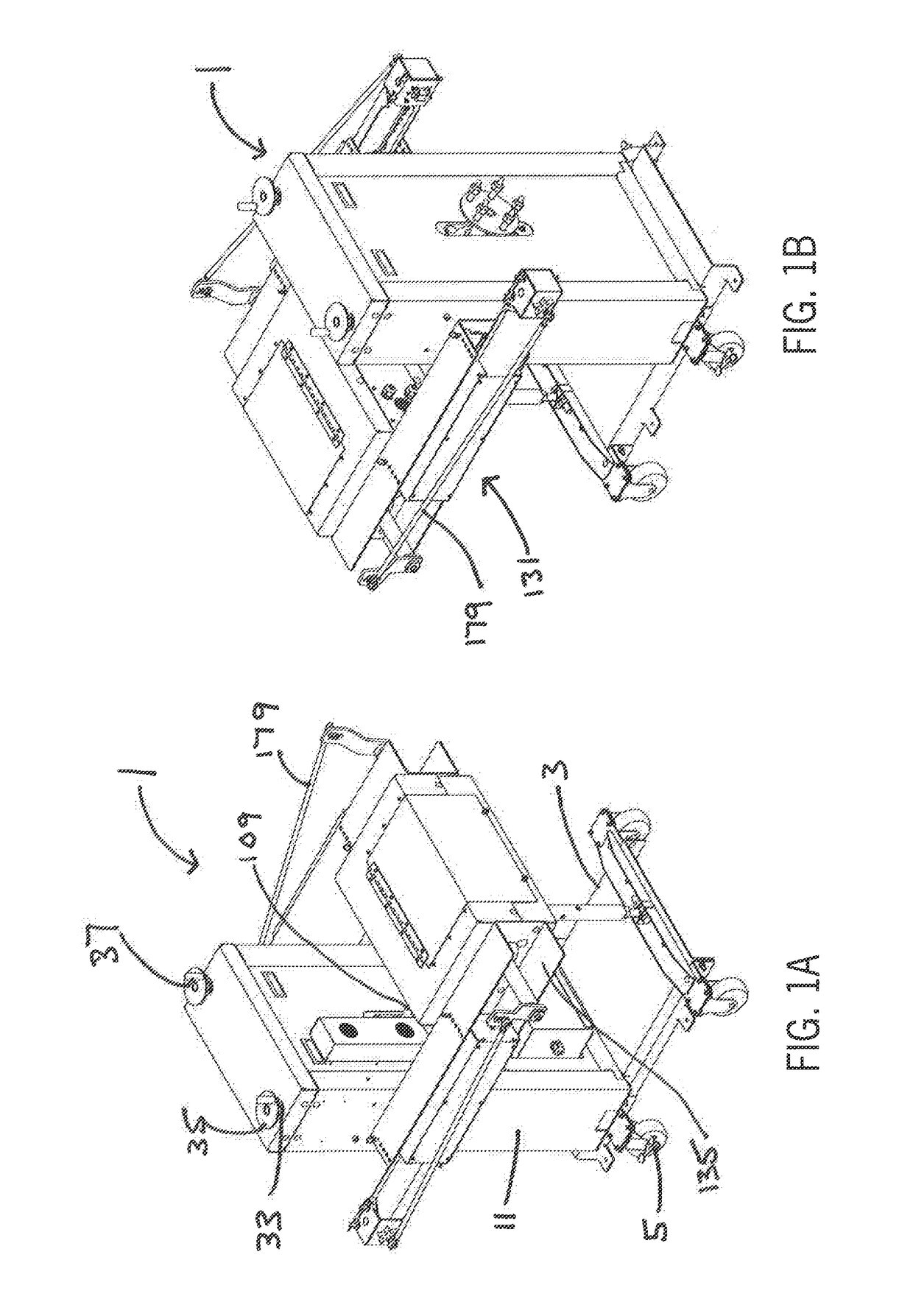
[0026]Now referring to the drawings in detail wherein like reference numerals refer to elements throughout, FIGS. 1A and 1B show assembly views of the automatic tire siping machine 1.

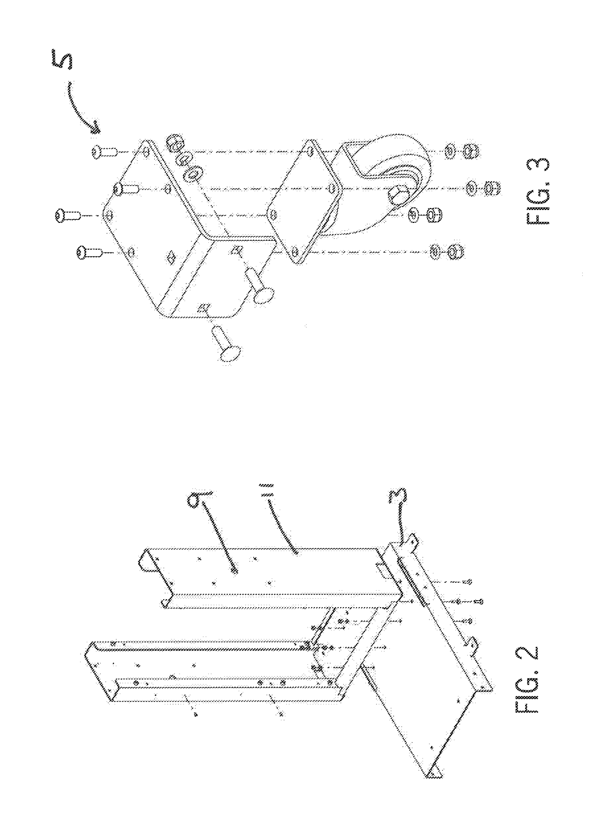
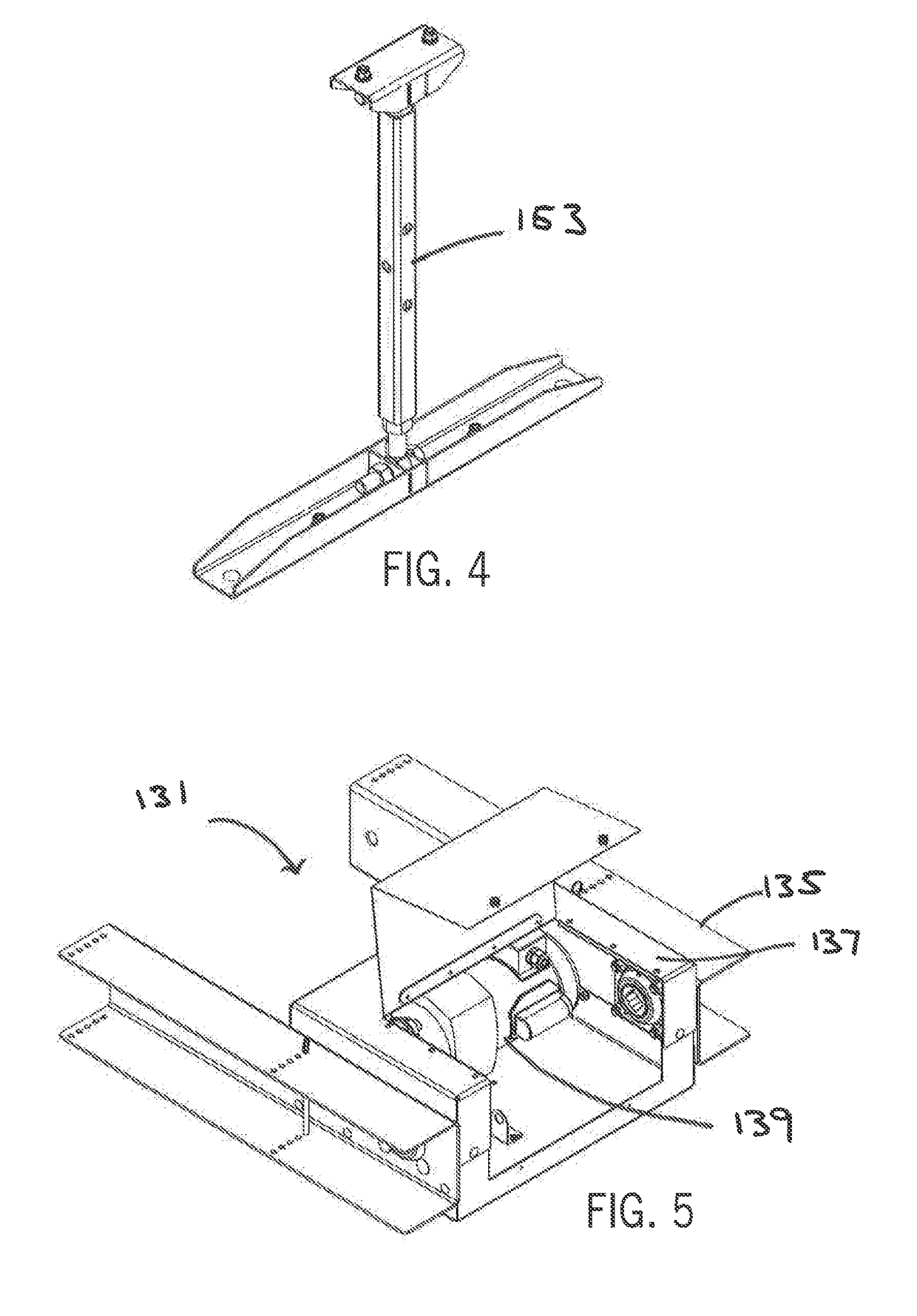
[0027]Referring now to FIG. 2, support structure for automatic siping machine 1 comprises chassis 3 and vertical support members 11 shown in more detail in FIG. 2. Chassis 3 is designed to be relatively mobile and generally provides accommodation slots 7 for the forks of a forklift such that automatic siping machine 1 can be easily moved. Chassis 3 may also include casters 5 such as those shown in FIG. 5 such that automatic siping machine 1 can be wheeled around manually. Chassis 3 further includes complementary apertures 9 on either side for use in connection with side channels 135 which help support motor carriage assembly 137, which is discussed in more detail below. Vertical support members 11 are rigidly attached to chassis 3 and are designed to provide fixed support for the carriage height adjustm...


PUM

PropertyMeasurementUnit
depthsaaaaaaaaaa
lengthaaaaaaaaaa
skid resistanceaaaaaaaaaa

Abstract

An automatic tire sipe forming machine for forming sipes of uniform depths and at uniform intervals across the circumferential surface of a tire. The automatic tire sipe forming machine includes means for indexing a tire a fixed rotational interval and a reciprocating mechanism for forming the sipes. The automatic tire sipe forming machine further includes means for changing the angle of the sipes and for accommodating various widths and sizes of tires.

Description

FIELD OF THE INVENTION[0001]The present invention generally relates to an automatic sipe forming machine for forming sipes on the tread face of a new tire or a retreaded tire for the purpose of improving traction and skid resistance.BACKGROUND OF THE INVENTION[0002]Conventional tire siping methods have been manual. Specifically, an operator manually forms grooves on a tread face to a predetermined depth using a knife or knives arranged in a parallel holder. This known process is extremely undesirable in that it is a manual operation that requires several hours and a significant amount of strength and precision to cut consistent sipes on the tread face of a single tire. Moreover, the manual tire siping operation itself is dangerous in that an operator is required to make repetitive applications of an extremely sharp knife over a relatively hard surface. Additionally, non-uniformities or irregularities of pitch, depth, angle and shape of the sipes are likely to occur, resulting in les...

Claims


Application Information

Patent Timeline
Patent Type & Authority Applications(United States)
IPC IPC(8): B29D30/68
CPCB29D30/68
Inventor COEL, MICHAEL J.
Owner 5 POINT FAB LLC
Learn More