This helps you quickly interpret patents by identifying the three key elements:
Problems solved by technology
Method used
Benefits of technology
Benefits of technology
This patent provides a commentary on a new lock design for doors that offers improved security, reliability, and ease of use. The lock is simple in construction, with minimal parts, and has been designed to reduce the likelihood of malfunctions. Its unique features have also been designed to make it more efficient and eliminate common issues.
Problems solved by technology
As hinted at, in this latter type of lock that has just been disclosed, the two parts of lock relating respectively to the latch and to the bolt are totally decoupled from one another both from the functional and structural point of view, which entails a significant general complexity with a high number of mechanical parts that are necessary for the relative operation thereof.
It is clear that this lock includes a great number of mechanical components that define a driving mechanism that is structurally rather complex, accordingly expensive to make, the mechanical reliability of which, which as known decreases with the complexity and number of parts of a structure, is adversely affected thereby.
From CH671427 another lock is known also having a significant structural complexity and thus being affected by the same drawbacks set out above and by an unsatisfactory level of security provided.
CH446109 relates to another lock that does not however provide the levels of security and versatility that it is desired to obtain.
Another drawback of known locks is due to the fact that the accidental driving of the key cylinder to lock the door when the latter is not actually closed on the respective door jamb entails some problems; in particular, the outward projection of the bolt causes, by bringing up the door to the door jamb, damage to the door jamb, the more serious the greater the impetus with which the door is pushed to the closed position.
Method used
Image
Click on the blue label to locate the original text in one second.
Reading with bidirectional positioning of images and text.
Examples
first embodiment
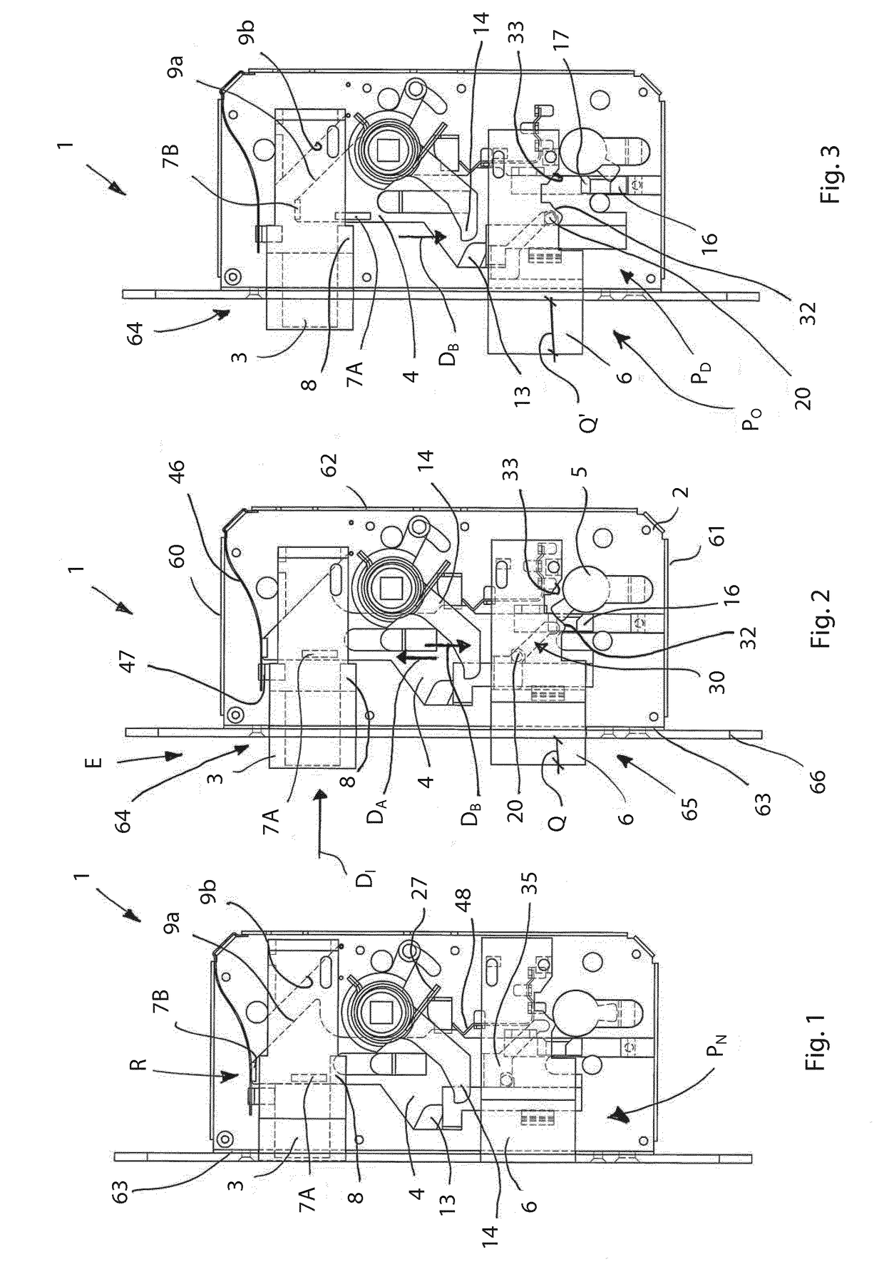
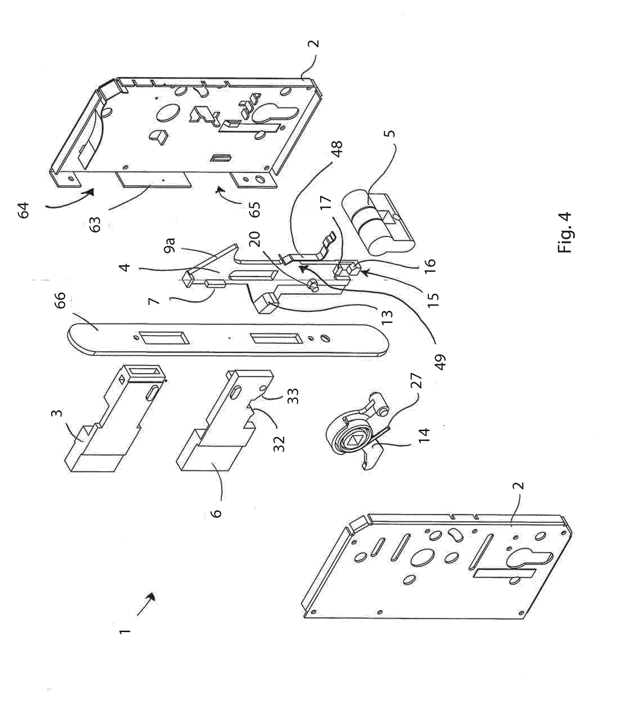
[0031]With reference to FIGS. 1 to 12, the lock 1 is disclosed. The lock 1 comprises a containing box body 2, for example in pressed sheet steel, suitable for being housed in a cavity obtained in the door rebate. The containing box body 2 consists of two half shells that are mutually couplable to bound a chamber for the various components of the lock. The two half shells together define an upper wall 60, a lower wall 61, two lateral parallel walls, a rear wall 62, and a front wall 63 provided with respective upper 64 and lower 65 openings arranged for enabling a latch 3 and a bolt 6, which will be disclosed below, to exit.
[0032]A frontal closing plate 66 is provided that, once inserted the box body 2 inside the cavity of the door, is applied to the front wall 63 fixed by the same screws that fix the lock 1 to the door.
[0033]The lock 1 comprises a latch 3 or 3′ that is movable, along an entrance direction DI, between an extracted position E, i.e. protruding outside the box body 2, an...
embodiment 1
[0035]For the sake of simplicity, (in FIGS. 1 to 4) only the lock embodiment 1 with magnetic latch 3 is shown, the embodiment with mechanical latch 3′ (shown in FIGS. 9, 10, 10A) being functionally and structurally identical apart from details that will be made clear below.
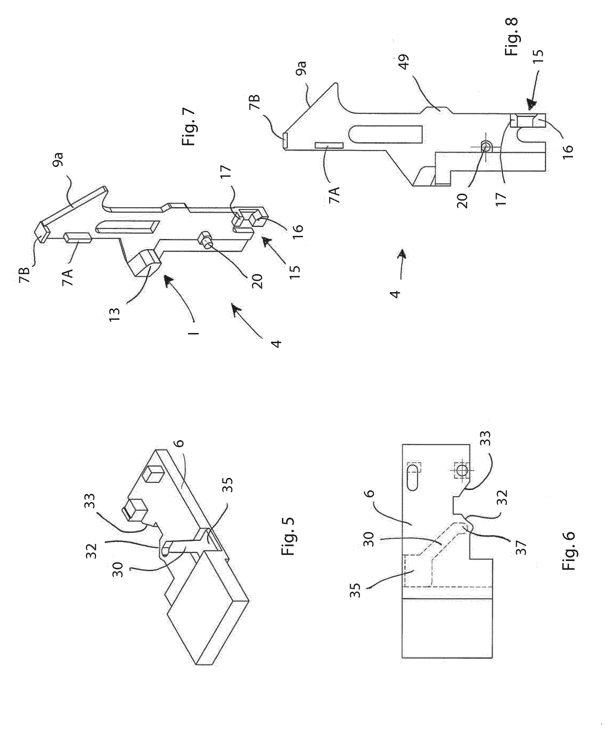
[0036]The lock comprises a driving device 4 that is movable along an opening direction DA to move the latch 3 from the extracted position E to the retracted position R. The driving device 4 is movable along the aforesaid opening direction DA by a rotatable lever member 14 that is in turn drivable by an outer control handle.
[0037]In particular, the opening direction DA is transverse to the entrance direction DI along which the latch 3 is movable.
[0038]To move the latch 3 from the extracted position E to the retracted position R, the lock 1 is provided with a motion transferring arrangement (9a, 9b; 10a, 10b, 11), disclosed better below, which transforms a movement of the driving device 4 along the opening direction...
embodiment 101
[0045]In one embodiment (not shown), it is possible to provide, in replacement of just one of the two tilted surfaces 9a and 9b, a wheel portion, or another equivalent solution, which is able to slide on the remaining tilted surface. This possible configuration can also be applied to the lock embodiment 101 that will be disclosed further on.
[0046]Still with reference to FIGS. 1 to 12, the cursor element 4 comprises an engaging lug 13, placed in an intermediate zone 1 of the cursor element 4 (FIG. 7), and suitable for coupling with the lever member 14 that is drivable by the outer handle. When the lever member 14 couples with the engaging lug 13, the cursor element 4 can be advanced along the opening direction DA. Basically, a nose portion of the lever member 14 acts on a lower zone of the engaging lug 13 by pushing upwards the cursor element 4 that can in this way retract the latch 3 (or 3′) into the containing box body 2. The lever member 14 is urged elastically to a rest position ...
PUM
Abstract
A lock for a door of the rebated type, comprises a containing box body, that is suitable for being housed in a cavity of the door, a latch that is movable between an extracted position and a retracted position in the box body and a driving device that is movable by means of a control handle, along an opening direction to move the latch from the extracted position to the retracted position. The driving device is movable, by a key-locking-member, along a locking direction opposite the opening direction, to reach a disengaged position in which the driving device is not engageable by the control handle so as to prevent driving of the latch. A bolt is provided that is movable, by means of the key-locking-member, from a non-operative position, in which it is retracted into the box body, to an operative position protruding outside the box body. The driving device comprises a locking arrangement shaped for locking the latch in the extracted position, preventing forced movement thereof from the outside to the retracted position, when the driving device is in the disengaged position in which is not engageable by the control handle.
Description
CROSS-REFERENCE TO RELATED APPLICATIONS[0001]This application is a § 371 National Stage entry of PCT International Application No. PCT / EP2017 / 054794 filed Mar. 1, 2017. PCT / EP2017 / 054794 claims priority to Italian Application No. UB2016A001253 filed Mar. 2, 2016. The entire content of these applications is incorporated herein by reference.BACKGROUND OF THE INVENTION[0002]The present invention relates to a lock for a door, in particular for a rebated door.PRIOR ART[0003]Locks for a rebated door are known comprising a containing box body inside which a latch is fitted that is movable from an extracted position, with respect to the box body, to a retracted position in the box body. When the door is closed, with the rebate thereof next to the door jamb, the latch in the extracted position is received in a corresponding cavity obtained on the door jamb, this cavity being bounded by a retaining plate. By a handle that is drivable from the outside it is possible to act on the latch to tran...
Claims
Application Information
Patent Timeline
Application Date:The date an application was filed.
Publication Date:The date a patent or application was officially published.
First Publication Date:The earliest publication date of a patent with the same application number.
Issue Date:Publication date of the patent grant document.
PCT Entry Date:The Entry date of PCT National Phase.
Estimated Expiry Date:The statutory expiry date of a patent right according to the Patent Law, and it is the longest term of protection that the patent right can achieve without the termination of the patent right due to other reasons(Term extension factor has been taken into account ).
Invalid Date:Actual expiry date is based on effective date or publication date of legal transaction data of invalid patent.

