Rotateable endcap / base for tube lamps

a technology of end caps and tubes, applied in the field of lamps, can solve the problems of safety hazards, loosening or damage of the connection, and the torque occurring during the installation of the lamp into the socket must be absorbed by the rotary mechanism, and achieve the effect of less space and significantly simplified production of the lamp according to the invention

Active Publication Date: 2019-02-28
LEDVANCE GMBH
View PDF0 Cites 2 Cited by
  • Summary
  • Abstract
  • Description
  • Claims
  • Application Information

AI Technical Summary

Benefits of technology

[0014]The base of the lamp has a base sleeve, which is rotatably mounted relative to the bulb. The base sleeve can be made, for example, of plastic. The electronic driver is arranged at least partially in the base sleeve. The electronic driver is preferably rotationally fixedly connected to the base sleeve, i.e. when the base sleeve rotates relative to the bulb the electronic driver also moves correspondingly. As a result, a mechanical loading of the electrical connection between the electrical connecting elements fastened to the base sleeve and the driver is avoided. The electronic driver can be connected on the input side to the electrical connecting elements in particular by soldering or crimping.
[0037]The rotatable connection of the base and the bulb described here uses fewer individual parts than the known solutions for a rotary mechanism with springs. As a result, the production of a lamp according to the invention is significantly simplified. Furthermore, the rotatable connection described here requires substantially less space than the known solutions. In this way more space is available for the light engine and the unlit region of the lamp is smaller. The visible part of the base sleeve made from plastic can be very short relative to the cover sleeve made from metal. As a result, the lamp looks very similar to a conventional fluorescent tube lamp with a purely metal base.

Problems solved by technology

Moreover, the torque occurring during installation of the lamp into a socket must be absorbed by the rotary mechanism.
Loosening of or damage to this connection can constitute a safety risk due to the applied mains voltage.

Method used


Image

  • Rotateable endcap / base for tube lamps
  • Rotateable endcap / base for tube lamps
  • Rotateable endcap / base for tube lamps

Examples


Embodiment Construction

[0046]Preferred exemplary embodiments are described below with reference to the drawings. In this case elements which are the same, similar, or act in the same way are provided with identical reference numerals in the different drawings, and repeated description of some of these elements is partially omitted in order to avoid redundancies.

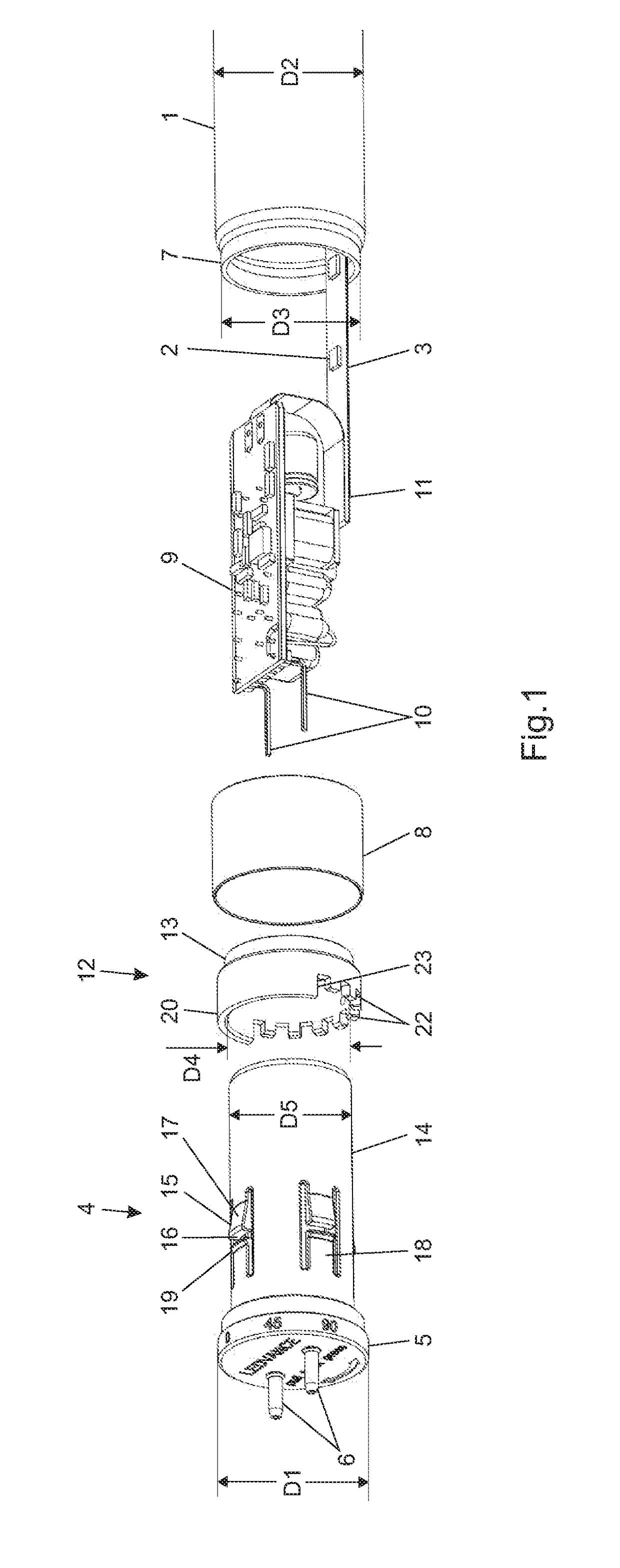
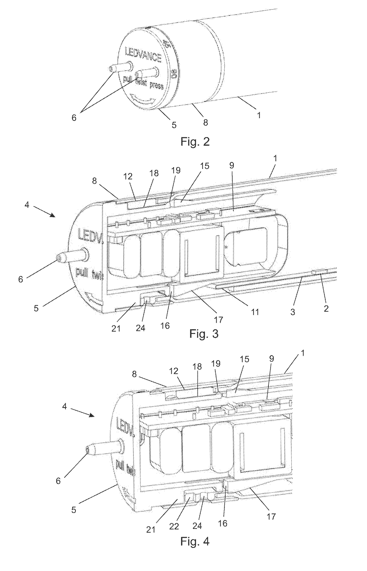
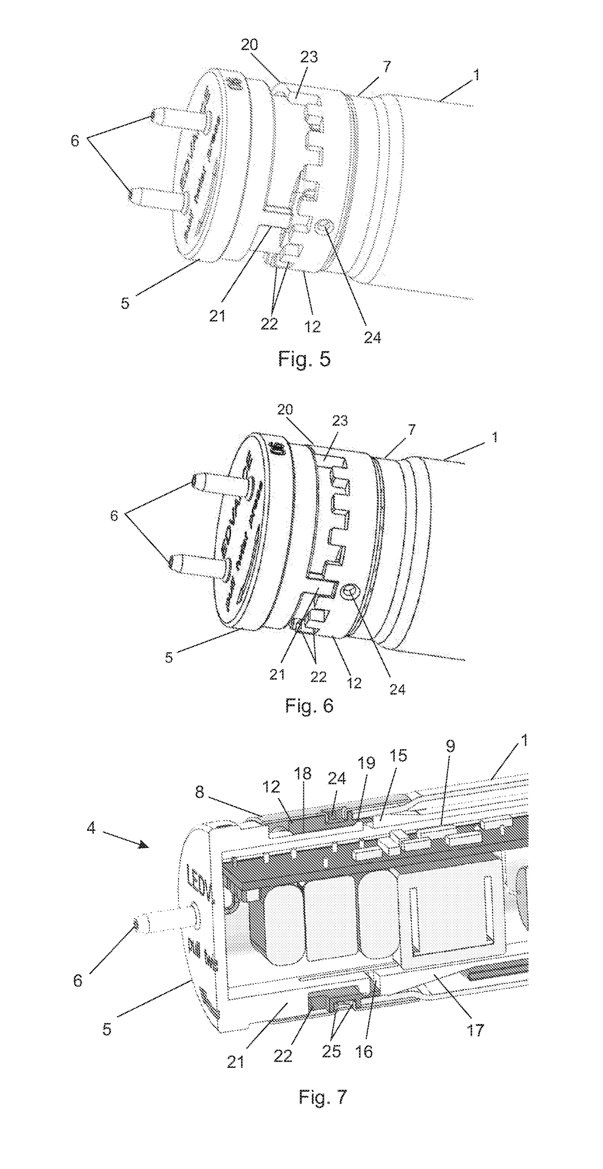
[0047]An embodiment of a lamp according to the invention is shown schematically in FIGS. 1 to 6 in different representations and positions. Only one end of the lamp is shown in each drawing. FIG. 1 shows a perspective exploded view of the individual components of the lamp. In FIG. 2 the lamp is illustrated in the assembled state, specifically in the fixing position, i.e. the end cap is not rotatable. FIGS. 3 and 4 show the lamp in a perspective sectional representation, in one case in the fixing position (FIG. 3) and in one case in the rotation position (FIG. 4), in which the end cap is rotatable.

[0048]The lamp has a translucent (for example matte)...


PUM


Abstract

A lamp includes a base with at least two electrical connecting elements. A bulb is rotatably mounted relative to the base. A light engine is arranged in the bulb with at least one light-emitting element and an electrically conductive substrate on which the light-emitting element is arranged. An electronic driver is connected to the electrically conductive substrate for activation of the light-emitting element. The base has a base sleeve in which the electronic driver is arranged. The electrically conductive substrate has a flexible connecting section between the electronic driver and the light-emitting element.

Description

CROSS-REFERENCE TO RELATED APPLICATIONS AND PRIORITY[0001]This patent application claims priority from German Patent Application No. 102017120067.3 filed Aug. 31, 2017, which is herein incorporated by reference in its entirety.TECHNICAL FIELD[0002]The present invention relates to a lamp with a base and a bulb rotatably connected to the base. In particular the present invention relates to retrofit LED tube lamps.BACKGROUND[0003]Conventional fluorescent tubes (low-pressure discharge lamps, for example the models T5 and T8) by their nature emit generated light in all directions around the longitudinal axis of the tube. Because retrofit tube lamps in LED technology have LEDs arranged in a line, these lamps generally have a limited emission angle which is determined by the emission characteristic of the LEDs.[0004]In order to enable a targeted emission of the light depending upon the application, there are retrofit LED tube lamps in which the lamp bases (also referred to as end caps) are...

Claims


Application Information

Patent Timeline
Patent Type & Authority Applications(United States)
IPC IPC(8): F21K9/235F21V23/06F21V17/12F21V23/00F21K9/237F21K9/238F21V17/18
CPCF21V17/18F21V23/006F21K9/235F21K9/238F21V17/12F21Y2115/10F21K9/237F21V23/06F21K9/65F21K9/272
Inventor ECKERT, KLAUSPILHOEFER, BERNDWAGNER, FLORIAN
Owner LEDVANCE GMBH
Why Eureka
Try Eureka