System and method for determining the relative direction of an RF transmitter

a technology of relative direction and rf transmitter, which is applied in the direction of direction finders, instruments, measurement devices, etc., to achieve the effect of small antennas, small and cheaper

Active Publication Date: 2019-02-28
HISEP TECH
View PDF11 Cites 6 Cited by
  • Summary
  • Abstract
  • Description
  • Claims
  • Application Information

AI Technical Summary

Benefits of technology

[0025]As opposed to prior-art DF techniques that need expensive receivers, (usually one receiving channel per each antenna) and operate on the IF (Intermediate Frequency) of the received signal, the methods of the subject matter operate directly on the RF (Radio Frequency), uses a small quantity of electronic non-expensive devices and is therefore much smaller and cheaper.

Problems solved by technology

The RF signal absorption may result from the electromagnetic-absorbing material which may be associated with the DF system and obstruct at least some of the antennas from receiving the full strength of the RF signal.

Method used


Image

  • System and method for determining the relative direction of an RF transmitter
  • System and method for determining the relative direction of an RF transmitter
  • System and method for determining the relative direction of an RF transmitter

Examples


Embodiment Construction

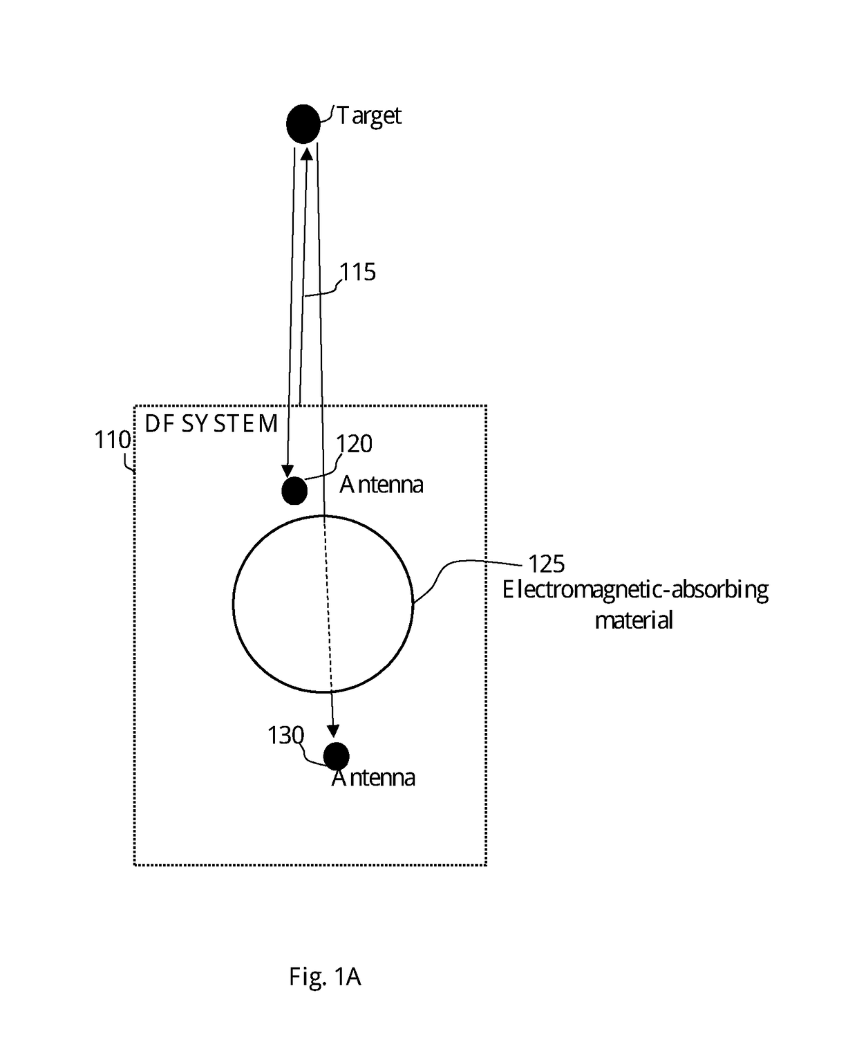
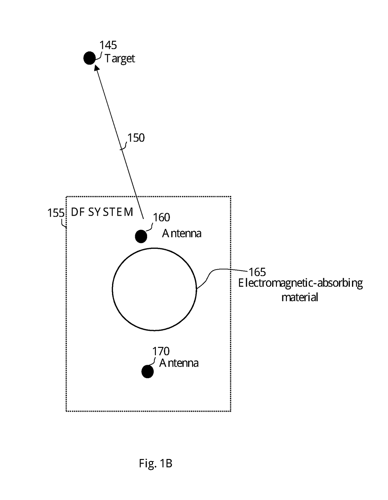
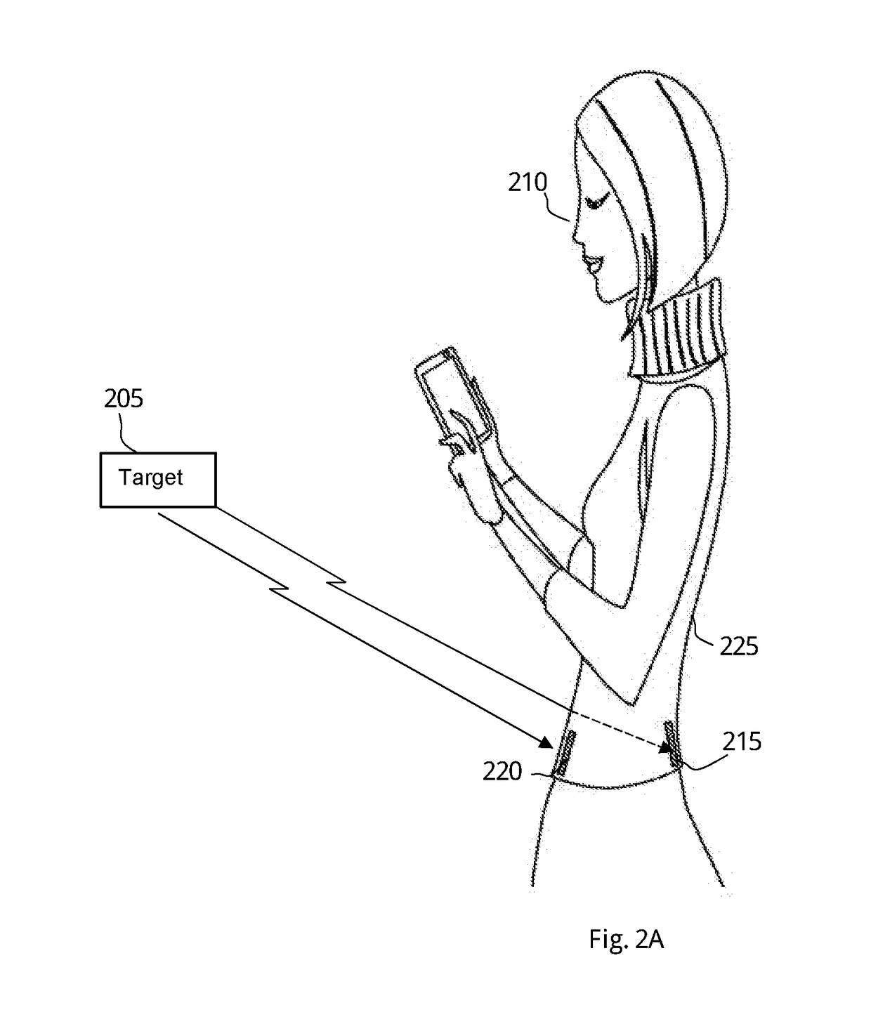
[0049]The present invention discloses a DF system and method to determine the relative direction of a target by utilizing electromagnetic-absorbing material and at least two antennas. The DF system comprises at least a pair of antennas designed to receive RF transmissions, a computerized unit configured to collect the RF signals received by the antennas and a memory unit to store the information received during the “relative direction determination” process. Such information may be directions of the targets, the number of targets, the absorption factor of the electromagnetic-absorbing material, the heading of the DF system, the alignment of the antennas versus each other and versus the absorbing material, and optionally additional information which may be related to the “relative direction determination” process. The DF system is designed to utilize a power source from an internal source such as a battery. In some cases, the DF system may be connected to an external power source suc...


PUM


Abstract

The subject matter discloses a method to determine a relative direction of a target RF transmitter, performed by a direction finding (DF) system comprising at least a pair of antennas having an electromagnetic-absorbing material between them, comprising conducting wireless communication between the target RF transmitter and each one of the antennas of the DF system, measuring the signal strength of the target RF transmitter received at each antenna, calculating the difference between the signal strength measured at each one of the antennas in the pair, and determining a relative direction of the target RF transmitter to be is the direction of the antenna within the pair of antennas in which the stronger signal was measured.

Description

FIELD OF THE INVENTION[0001]The present invention relates to the use of wave absorbing material in general, and the use of electromagnetic-absorbing material in particular to create a Direction-Finding (DF) system and method.BACKGROUND OF THE INVENTION[0002]In recent years there is a growing usage of wireless connectivity in almost every device. The growing commercial adoption of the “Internet of Things” (IoT) leads to a situation which multiple device and object types are designed to be coupled with wireless transmitters or wireless sensor nodes in order to enable internet communication on one hand, and direct connectivity to other devices or objects on the other hand. In some cases, the objects comprising the wireless transmitters or the wireless sensor nodes can be electronic devices, such as a mobile telephone, a tablet personal computer, and the like. In some other cases, the objects comprising the wireless transmitters or the wireless sensor nodes may be wearables, clothing an...

Claims


Application Information

Patent Timeline
Patent Type & Authority Applications(United States)
IPC IPC(8): G01S3/28G01S3/04
CPCG01S3/28G01S3/043G01S5/02
Inventor ERAD, YARIVVERED, GADERAD, MENACHEMVERED, URI
Owner HISEP TECH
Why Eureka
Try Eureka