Anesthetic vaporizer for a breathing apparatus and method for operation thereof to vaporize a liquid anesthetic agent

a technology of anesthetic vaporizer and breathing apparatus, which is applied in the direction of respirator, lighting and heating apparatus, combustion types, etc., can solve the problems of limited effect, high power not available at the vaporization site, and breathing apparatuses in which the injection vaporizer is used, so as to achieve advantageous vaporization

Active Publication Date: 2016-06-21
OSRAM OPTO SEMICON GMBH & CO OHG +1
View PDF5 Cites 1 Cited by
  • Summary
  • Abstract
  • Description
  • Claims
  • Application Information

AI Technical Summary

Benefits of technology

[0017]Embodiments of the invention provide for sufficient heat (or thermal) energy being available for reliably vaporizing, i.e. gasifying, the liquid that lands on a surface of the injection vaporizer when injected. The supply of necessary evaporation heat energy, that might not be provided form a heater element only, as explained above, is provideable by means of a phase change material (PCM). The PCM is arranged in a heat energy storage unit. The PCM provides for avoiding local temperature drops by locally bridging the delivery of evaporation heat at the surface where the liquid has landed. The PCM is thermally coupled to the surface. By providing a PCM that has a melting temperature above the evaporation temperature of the anesthetic agent, it is ensured that the temperature of the surface is permanently above the evaporation temperature. The term “evaporation temperature” in the present context is a desired temperature at which an anesthetic agent liquid evaporates, such as during operation of an anesthetic vaporizer. The evaporation temperature, or the boiling point, is for instance pressure dependent, but is lower at higher pressures than standard sea level atmospheric pressure. The PCM is chosen to have a phase shift temperature that exceeds a maximum evaporation temperature of a respective anesthetic agent in operative conditions of the anesthetic vaporizer.
[0018]Thus evaporation is facilitated. Evaporation is provided in a reliable manner. Thermal energy stored in the PCM of a heat energy storage unit provides for temperature stabilization during intermittent injection evaporation. Thermal Energy is provided as a cyclic, temporary storage of high temperature energy. The high temperature energy is provided to charge a PCM to the high temperature at least during time slots where no evaporation occurs. Thermal input energy may also be provided continuously to the PCM, i.e. also during evaporation. Thermal input energy provided to the PCM is usually provided in form of electrical energy converted to heat energy in a heater unit. The input energy is however lower than the peak thermal energy provideable thanks to the PCM from previous thermal charging thereof. In this manner, the PCM is provided to bridge a time gap between energy requirement and energy use. This has a number of advantages, including smaller heater units and / or smaller, cheaper injector vaporizers. Moreover, accumulation of liquid in the injection vaporizer is effectively prevented and evaporation of anesthetic agents is reliably provided.
[0019]In more detail, when a pulse of the injected liquid lands on the surface of a vaporization chamber or channel, the vaporization starts immediately. The temperature would now locally drop at the landing surface as the phase shift of the liquid anesthetic agent to the gasified anesthetic agent requires an amount of evaporation heat supplied by the surface. However, the PCM prevents a temperature drop below a phase shift temperature of the PCM, which is above the vaporization temperature of the anesthetic agent. Evaporation is thus continued rather than prevented as conventionally by the temperature drop. The thermal resistance between the PCM and the liquid on the surface is minimized. Thus the temperature may drop locally at the surface during evaporation, but will stay at a constant level at the phase shift temperature of the PCM. The PCM may solidify partly, but the amount of PCM is dimensioned that it will not entirely solidify until all liquid from an injected pulse is gasified. During a pause until the next injection pulse, the PCM is entirely liquefied again and the temperature of the PCM may be raised over the melting / solidification temperature to store sufficient heat energy for the next injected liquid pulse.
[0027]In some embodiments the vaporizer comprises an interior evaporation surface portion. An injecting unit is for instance provided for generating a pulsed, intermittent spray of the liquid towards the evaporation surface portion for evaporating the injected liquid at least partly from the evaporation surface when landing thereon. Further, a heat energy storage unit comprises a phase change material (PCM). The heat energy storage unit is thermally coupled to at least a portion of the evaporation surface. The PCM arranged in the heat energy storage unit has a phase shift temperature that is higher than the evaporation temperature of the anesthetic agent. In this manner the PCM is provided at least partly liquid at an operative temperature of the vaporizer. Vaporization is thus advantageously improved. Temperature at an evaporation surface is stabilized at a level above the evaporation temperature of the liquid.
[0028]According to a second aspect of the invention, a method of vaporizing an anesthetic agent liquid in an anesthetic vaporizer is provided. The method comprises providing a heat energy storage unit comprising a phase change material (PCM), which heat energy storage unit is thermally coupled to at least a portion of an evaporation unit. Further, the method has a step of intermittently adding a volume of the liquid from a delivery unit to the evaporation unit. Moreover, the method includes a step of evaporating at least a portion of the volume of the liquid from the evaporation unit. The PCM has a phase shift temperature, such as a solidification temperature or liquefaction temperature, which is higher than the evaporation temperature of the anesthetic agent. Thus the method provides for stabilizing a temperature of the evaporation unit during the evaporating.
[0035]Some embodiments of the invention provide for more heat energy being provideable momentarily for evaporation, compared to heating units dimensioned for a medium temperature of the vaporizer chamber. A lower mean power may be provided to a heater unit than necessary for maintaining a vaporization chamber of a vaporizer, such as an injection vaporizer, at an operational temperature. Peak heat energy needed during vaporization of the spray is provided by the PCM. Thus, vaporization is provided in an energy efficient manner. Accumulation of liquid, such as in pools in the vaporization chamber, is effectively avoided. AS the PCM is locally arranged at the evaporation surface only, a relatively small volume of PCM needed compared to a PCM arranged to keep an entire reservoir of liquid at a desired temperature (which moreover would be below the evaporation temperature of the liquid to avoid unintentional or uncontrolled evaporation of the liquid, contrary to the present embodiments). The reservoir may now even be located remotely from the evaporation chamber of the vaporizer.

Problems solved by technology

However, such high power is not available at the vaporization site.
In addition, breathing apparatuses in which the injection vaporizers are used, have limited effect available due to safety requirements concerning battery backup drift, limiting available power.
Moreover, temperature regulation is slow as feedback is thermistor based.
However, due to a low thermal capacity of the volume available for the vaporization process, temperature drops quickly in the vaporization chamber following the injection pulse.
This temperature drop may lead to such low temperatures that the vaporization of the liquid injected anesthetic agent ceases.
This would be undesired in clinical operation
The latent heat storage device of DE4105370 is arranged to keep the entire vaporizer device at a constant temperature below the vaporization temperature and is furthermore not suitable to compensate for such quick, locally occurring temperature changes inside a vaporizing chamber of modern injection vaporizers.

Method used


Image

  • Anesthetic vaporizer for a breathing apparatus and method for operation thereof to vaporize a liquid anesthetic agent
  • Anesthetic vaporizer for a breathing apparatus and method for operation thereof to vaporize a liquid anesthetic agent
  • Anesthetic vaporizer for a breathing apparatus and method for operation thereof to vaporize a liquid anesthetic agent

Examples


Embodiment Construction

[0046]Specific embodiments of the invention will now be described with reference to the accompanying drawings. This invention may, however, be embodied in many different forms and should not be construed as limited to the embodiments set forth herein; rather, these embodiments are provided so that this disclosure will be thorough and complete, and will fully convey the scope of the invention to those skilled in the art. The terminology used in the detailed description of the embodiments illustrated in the accompanying drawings is not intended to be limiting of the invention. In the drawings, like numbers refer to like elements.

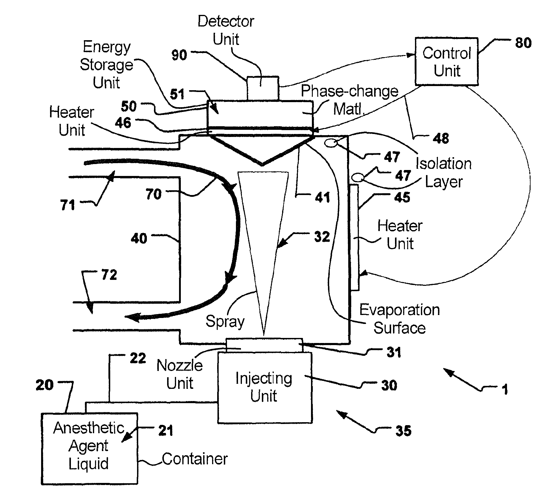
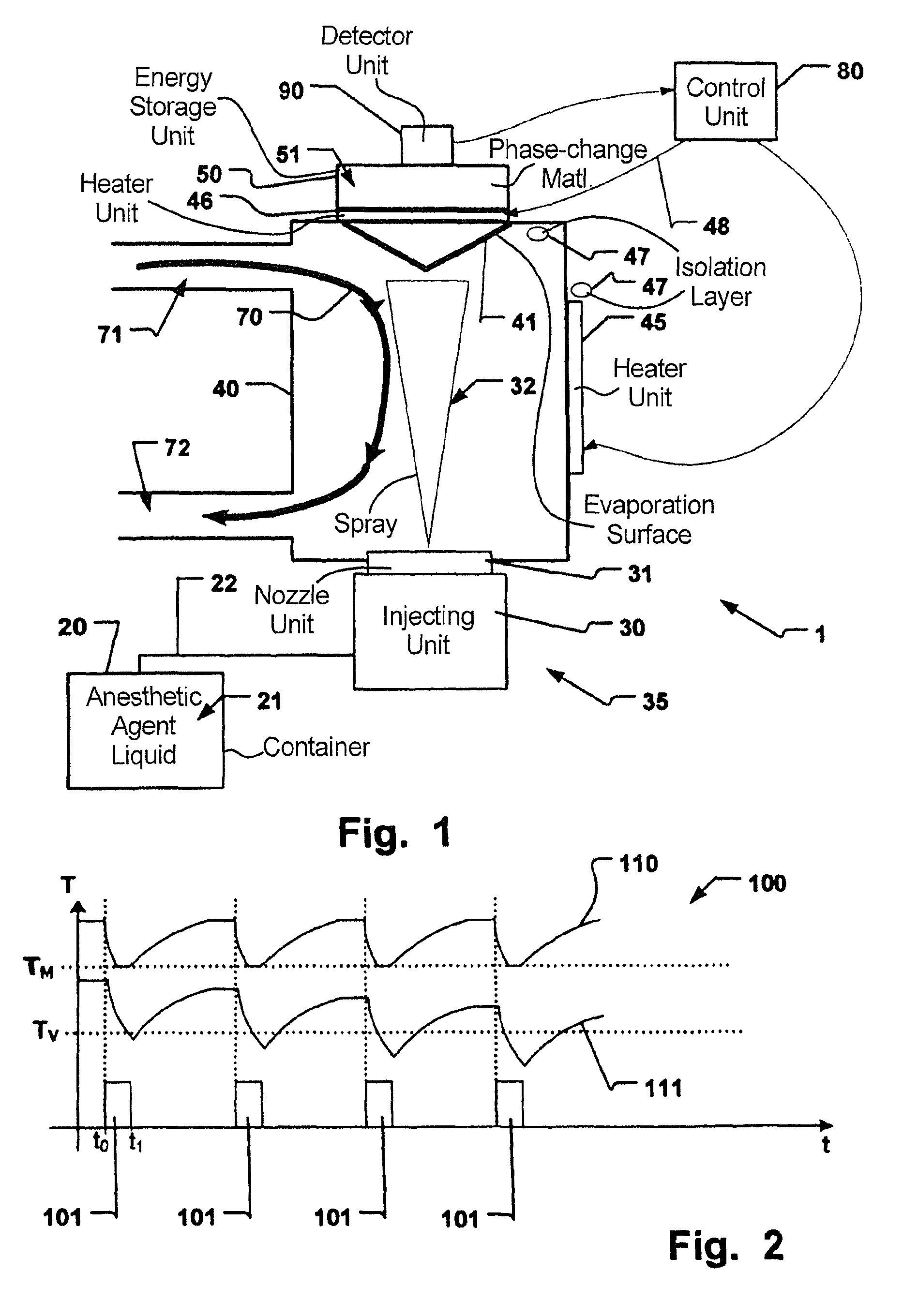
[0047]In an embodiment of the invention according to FIG. 1, an anesthetic vaporizer in form of an injection vaporizer 1 is provided. The injection vaporizer 1 is arranged for vaporizing an anesthetic agent liquid 21. The injection vaporizer 1 comprises an interior evaporation surface portion 41. The interior surface portion 41 is usually arranged inside the i...


PUM


Abstract

In an anesthesia vaporizer for vaporizing an anesthetic agent liquid and a method of vaporizing an anesthetic agent liquid in an vaporizer, an evaporation unit evaporates the anesthetic agent, a delivery unit intermittently adds a volume of said liquid to the evaporation unit in order to evaporate at least a portion of the volume of the liquid from the evaporation unit. A heat energy storage unit includes a phase change material (PCM) and is thermally coupled to at least a portion of the evaporation unit. The PCM has a phase shift temperature that is higher than the evaporation temperature of the anesthetic agent. The PCM in the heat energy storage unit is preferably at least partly liquid at an operative temperature of the vaporizer.

Description

BACKGROUND OF THE INVENTION[0001]1. Field of the Invention[0002]This invention pertains in general to the field of vaporizing devices and methods for breathing apparatuses, in particular anesthetic vaporizers. More particularly the invention relates to an anesthesia injection vaporizer device and method for vaporizing a liquid anesthetic agent in a breathing apparatus.[0003]2. Description of the Prior Art[0004]German published patent application number DE4105370 of Drägerwerk AG, published in 1992, discloses an anesthetic vaporizer device. The vaporizer is of the evaporation vaporizer type, as disclosed in German published patent application number DE1271903. A liquid anesthetic agent is stored in a vessel. The liquid anesthetic agent is drawn up by a cylindrical wick. Air becomes saturated with the anesthetic agent by flowing past the wick. The liquid is kept at a constant low temperature by a latent heat storage device to avoid unintentional evaporation. This is in particular appl...

Claims


Application Information

Patent Timeline
Patent Type & Authority Patents(United States)
IPC IPC(8): A61M11/00A61M16/18A61M16/10
CPCA61M16/18A61M16/1075A61M2205/3368A61M2205/3646A61M16/147
Inventor LARSSON, .ANG.KETROILI, CARL
Owner OSRAM OPTO SEMICON GMBH & CO OHG
Why Eureka
Try Eureka