Miniature laser seeker electro-optics

a laser seeker and electrooptic technology, applied in the direction of optical radiation measurement, direction/deviation determining electromagnetic systems, instruments, etc., can solve the problems of low duty cycle, breakable moving parts of scanning components, and inability to implement such systems without scanning components and/or cameras, etc., to achieve low duty cycle, small size, and low cost

Inactive Publication Date: 2013-11-19
CUBIC CORP
View PDF6 Cites 1 Cited by
  • Summary
  • Abstract
  • Description
  • Claims
  • Application Information

AI Technical Summary

Benefits of technology

[0003]Techniques are disclosed for sensing a location of a laser and / or other optical signals. According to certain embodiments of the invention, an electro-optical assembly can include a detector array coupled to one or more lenses for detecting the signals. Outputs of the photo detectors can be processed using peak detection and / or other techniques to conserve power, help ensure detection, and avoid the need for moving parts.
[0010]Numerous benefits are achieved by way of the present invention over conventional techniques. For example, embodiments of the present invention can utilize wide field of view (FOV) detection so that scanning may not be necessary, thereby avoiding the need for moving parts. This can allow for a smaller, cheaper, more durable, and / or lower-power electro-optical device. Additionally, power-saving techniques are employed while preserving enough sensitivity to detect an optical signal in high-noise environments. These and other embodiments of the invention, along with many of its advantages and features, are described in more detail in conjunction with the text below and attached figures.

Problems solved by technology

It can be difficult, however, to implement such systems without scanning components and / or cameras.
Problematically, however, scanning components have breakable moving parts, and both scanning components and cameras can have difficulty detecting a narrow-pulse laser designation signal with a low duty cycle, especially in high-noise (e.g. daylight) conditions.

Method used


Image

  • Miniature laser seeker electro-optics
  • Miniature laser seeker electro-optics
  • Miniature laser seeker electro-optics

Examples


Embodiment Construction

[0017]The ensuing description provides preferred exemplary embodiment(s) only, and is not intended to limit the scope, applicability or configuration of the disclosure. Rather, the ensuing description of the preferred exemplary embodiment(s) will provide those skilled in the art with an enabling description for implementing a preferred exemplary embodiment. It is understood that various changes may be made in the function and arrangement of elements without departing from the spirit and scope as set forth in the appended claims.

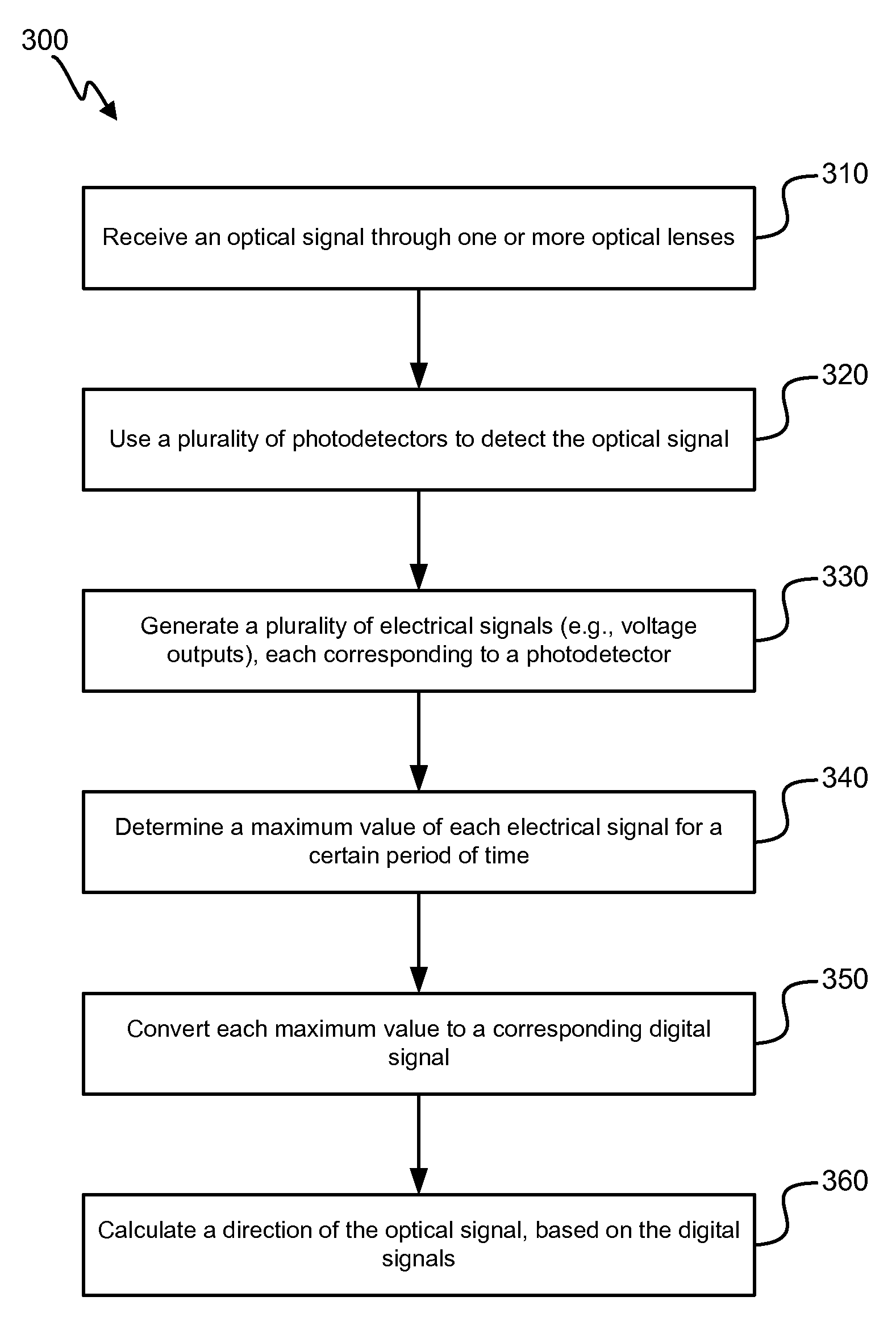
[0018]Light detection is a key component of various optical-sensing devices. Laser range finding, target acquisition, combat identification, laser tracking, space-to-ground communication, and other applications require light detection to capture and process light signals from a remote light source, such as a pulsed laser. This light detection is typically performed by a light sensor in an optical system of an optical device, which allows light to be directed ...


PUM

PropertyMeasurementUnit
lengthaaaaaaaaaa
widthaaaaaaaaaa
wavelengthaaaaaaaaaa

Abstract

Techniques are disclosed for sensing a location of laser and / or other optical signals. According to certain embodiments of the invention, an electro-optical assembly can include a detector array coupled to one or more lenses for detecting the signals. Outputs of the photo detectors can be processed using peak detection and / or other techniques to conserve power, help ensure detection, and avoid the need for moving parts.

Description

CROSS-REFERENCES TO RELATED APPLICATIONS[0001]The present application claims benefit under 35 USC 119(e) of U.S. Provisional Application No. 61 / 486,196, filed on May 13, 2011 of which the entire disclosure is incorporated herein by reference for all purposes.BACKGROUND[0002]Light detection in optical devices can take on various forms, according to the form and function of the optical device, among other concerns. For example, systems for detecting a laser (or other optical) designation signal can be incorporated into munitions-guidance systems. It can be difficult, however, to implement such systems without scanning components and / or cameras. Problematically, however, scanning components have breakable moving parts, and both scanning components and cameras can have difficulty detecting a narrow-pulse laser designation signal with a low duty cycle, especially in high-noise (e.g. daylight) conditions.BRIEF SUMMARY[0003]Techniques are disclosed for sensing a location of a laser and / or ...

Claims


Application Information

Patent Timeline
Patent Type & Authority Patents(United States)
IPC IPC(8): G01J1/00
CPCG01J1/0411G01S3/781G01S3/783G01J1/4228F41G7/226F41G7/2293Y10T29/49117
Inventor MARYFIELD, TONYTRISSEL, RICHARDROBINSON, DAVID A.PARRY, ROBERT WILLIAM
Owner CUBIC CORP
Why Eureka
Try Eureka