Hoisting system for installing a wind turbine

Active Publication Date: 2021-11-16
LAGERWEY WIND BV
View PDF23 Cites 0 Cited by
  • Summary
  • Abstract
  • Description
  • Claims
  • Application Information

AI Technical Summary

Benefits of technology

[0008]At first sight the expert in the art would never design such a hoisting system since it seems incapable of hoisting the maximum hoist. Surprisingly one should realize that by using the combination of the first hoisting device and the crane which was used to install the first hoisting device, there is sufficient capacity. The amazing result is that the first hoisting device can be lighter, thus less expensive and that the loads it will exert on the turbine are less, so that the joints can be cheaper and that the hoisting system is capable of hoisting the heaviest part. Advantageously the hoisting system distributes the hoist load over at least the first and another hoisting device. This way both systems can be dimensioned for a lower maximum load and thus will be cheaper and lighter.
[0009]Another benefit of an embodiment of the invention is that wherein the hoist is hoisted by two hoisting cables, each fixed at one end to the hoist and at the other end to a different hoisting device, so that it can be controlled better and becomes less sensitive to the wind. The hoist can be positioned more accurately which speeds up the installation process and reduces the risk of a damaging collision between the hoist and the already installed part of the wind turbine.
[0017]According to an embodiment of the invention the second hoisting device is a crane which is installed to the tower of the wind turbine, possibly with the ability to climb along the tower. Such a second hoisting device can be smaller and cheaper if it does not need to hoist the heaviest part alone. Also the loads transferred to the tower by such a second hoisting device are less and thus less tower strengthening is required, which further reduces the costs. According to this embodiment of the invention the heaviest parts are hoisted by the first hoisting device and by the second hoisting device.
[0022]In an embodiment the hoisting system further comprises a control system which uses data on the stand and loading of both the first and the second hoisting devices to control both devices and in particular which uses the measured loads of the first hoisting device to control the operation of the second device and more in particular also uses the loads of the second hoisting device to control the operation of the first hoisting device. Such a control system avoids that operation of the first hoisting device causes an overload of the second device and the other way around,
[0026]In an embodiment of the hoisting system comprises a first hoisting device which comprises means for supporting it on the yawing part of the turbine under construction, a second hoisting in the form of a climbing crane and a third hoisting device in the form of a relatively small industrial crane. The industrial crane installs the climbing crane. The climbing crane installs the higher tower segments, the main frame and the nacelle and the first hoisting device. The first hoisting device together with the climbing crane subsequently install the direct drive generator, the hub and the blades. The advantage of this hoisting system using this hoisting method is that a large industrial crane is not required for an onshore wind turbine. In the case of an offshore turbine, the use of a largest lifting vessel or a jack-up is avoided, by using the climbing crane to install the first hoisting device and subsequently using the first hoisting device and the climbing crane for hoisting the yawing part of the wind turbine in part or in a single hoist.

Problems solved by technology

At first sight the expert in the art would never design such a hoisting system since it seems incapable of hoisting the maximum hoist.

Method used


Image

  • Hoisting system for installing a wind turbine
  • Hoisting system for installing a wind turbine
  • Hoisting system for installing a wind turbine

Examples


Embodiment Construction

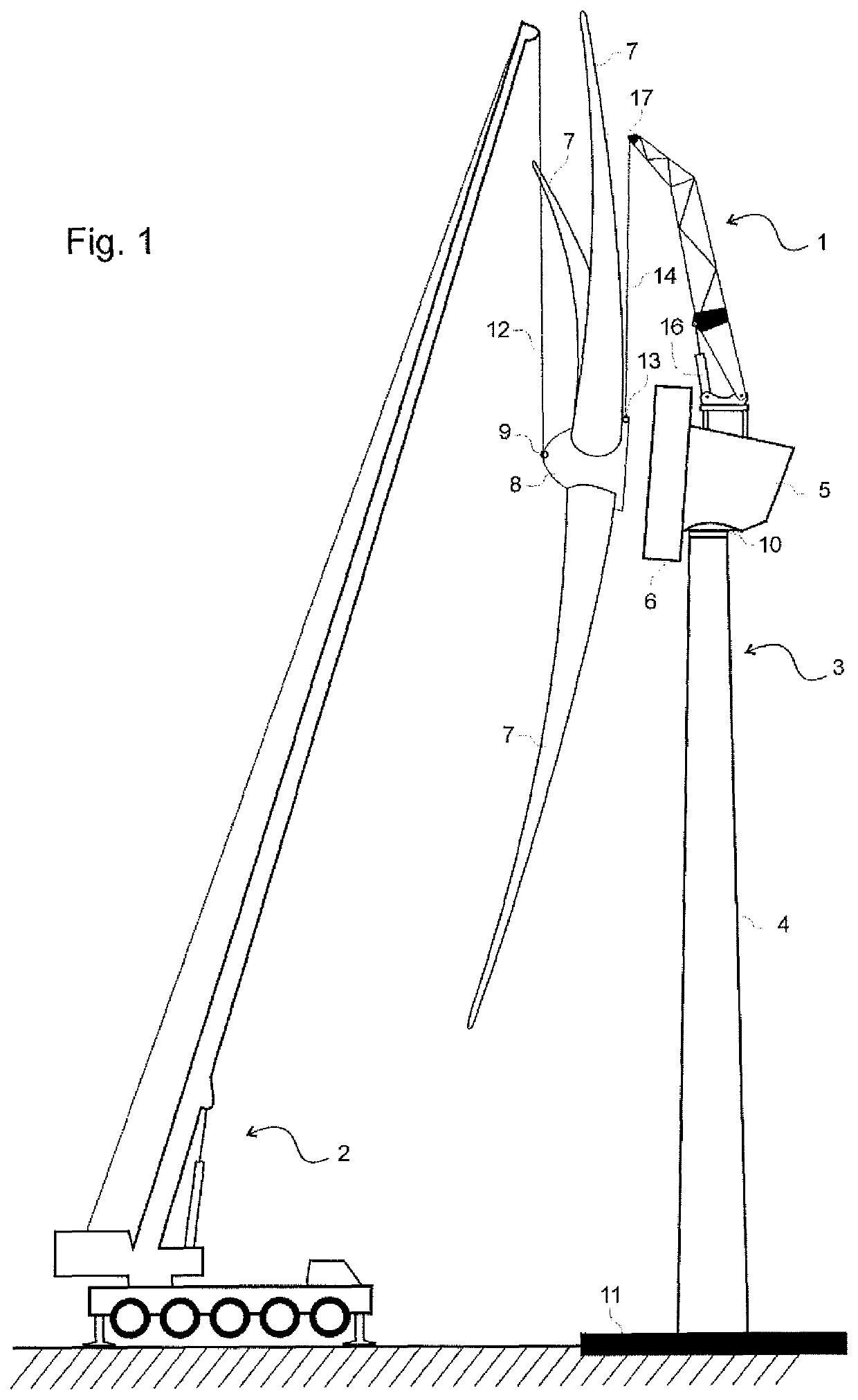
[0034]FIG. 1 shows a hoisting system comprising a first hoisting device 1 and a second hoisting device 2 which is used for the installation of a wind turbine under construction 3. The wind turbine comprises a foundation 11, a tower 4 and a yaw bearing 10. The yawing part comprises a nacelle 5, a direct drive generator 6 and a rotor which comprises a hub 8 and one or more blades 7. The rotor may be the heaviest part. The first hoisting device is supported on the yawing part of the wind turbine and comprises a beam 15 and a hoisting cable 14 which is fixed to hoisting point 13 of the rotor. The second hoisting device comprises a hoisting cable 12 and is fixed to hoisting point 9 of the rotor. It further comprises actuator 16 which allows for an inter alia horizontal movement of the lifting point 17.

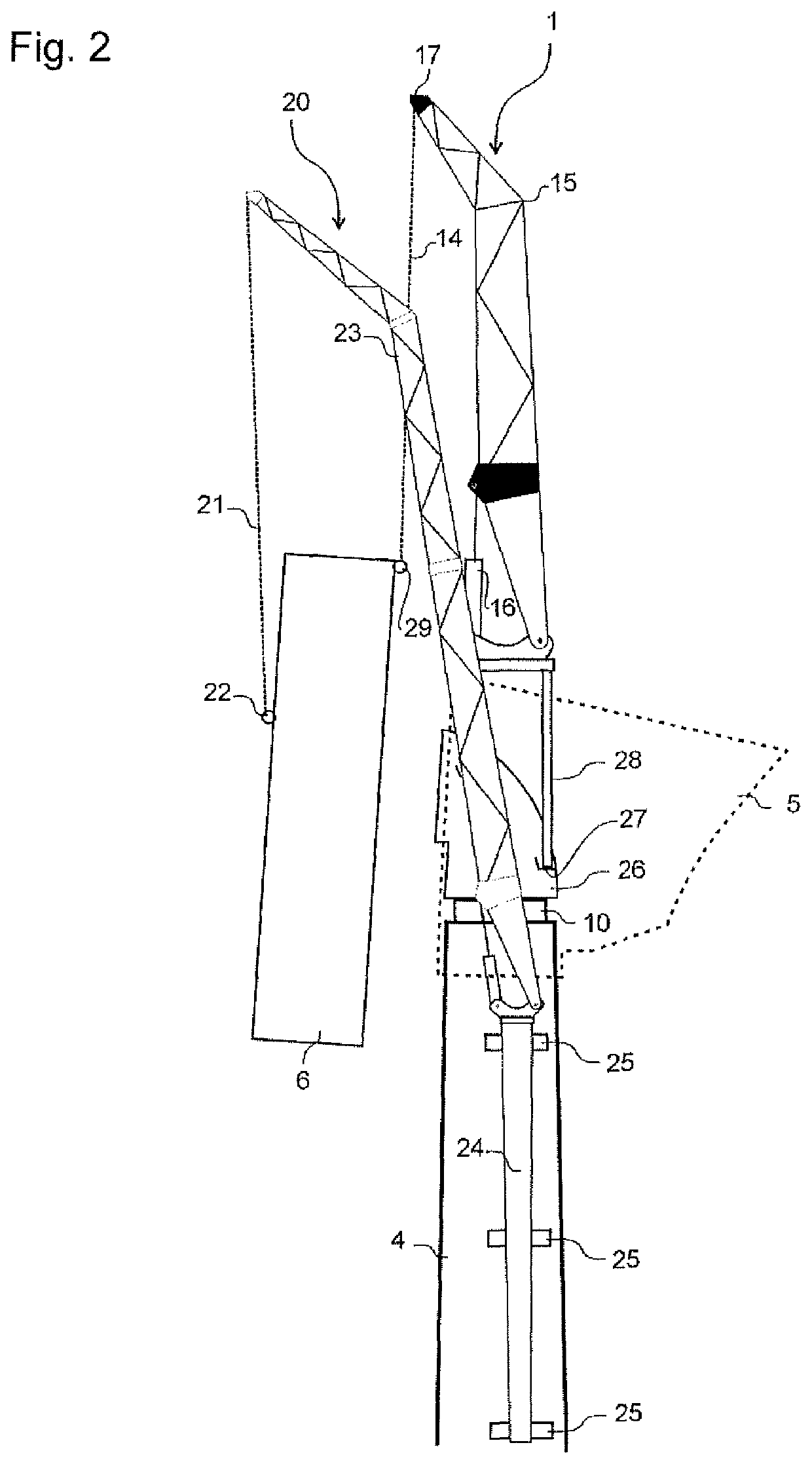
[0035]FIG. 2 shows another hoisting system comprising a first hoisting device 1 and a second hoisting device 20, which is used for the installation of a wind turbine under construction. The...


PUM


Abstract

A hoisting system for the at least one of an installation, a decommissioning and a maintenance of a wind turbine which comprises at least a foundation, a tower, a yawing part and a rotor of at least 80 m diameter with at least one blade, comprising a first hoisting device which comprises measures to establish a load carrying joint with an already built part of the wind turbine which is located above the foundation, wherein the hoisting system is characterized in that the ratio between the maximum hoist load of the hoisting device and the mass of the heaviest part is larger than 0.2 and smaller than 1 and in particular smaller than 0.8 and more in particular smaller than 0.7 and preferably smaller than 0.6, with the heaviest part being a heaviest part which is hoisted as one piece and which belongs to the yawing part of wind turbine.

Description

BACKGROUNDTechnical Field[0001]The present invention relates to a hoisting system for the installation of a wind turbine.Description of the Related Art[0002]The costs of labor and maintenance of wind turbines increase only gradually with increasing turbine size, and therefore to minimize costs, wind turbines are getting bigger and bigger. With increasing size and height, the installation costs of the turbines are not rising gradually but at least linearly with turbine size. The largest industrial cranes available are required to install the largest land-based wind turbines. Those heavy modular crane units are expensive, often require strengthening of the roads and special transportation permits. In addition to these disadvantages said cranes need a lot of space, which is not always available; and when such a crane is needed for the next turbine in a wind farm, it may occur that the crane cannot move thereto for example because the terrain is complex or the roads are too small. Then ...

Claims


Application Information

Patent Timeline
Patent Type & Authority Patents(United States)
IPC IPC(8): B66C23/20F03D13/10F03D80/50B66C23/18E04H12/34
CPCB66C23/207B66C23/185E04H12/34F03D13/10F03D80/50F05B2230/61F05B2240/916F05B2230/60F03D13/20Y02E10/728Y02P70/50Y02E10/72
Inventor PUBANZ, ANDRÉ HEINZLAGERWEIJ, HENDRIK LAMBERTUSVAN DE POL, AARTWAAIJENBERG, ALBERTUS
Owner LAGERWEY WIND BV
Why Eureka
Try Eureka