Visual Representation of Electromagnetic Signals Utilizing Controlled Electrostatic and Electromagnetic Vibration Energy within Transparent Conductive Enclosures

a technology of electromagnetic signal, which is applied in the field of visual representation of electromagnetic signals utilizing controlled electrostatic and electromagnetic vibration energy within transparent conductive enclosures, can solve the problems of not being able to display sounds in real time, not being able to display sound in three-dimensional real world space, and not being able to easily allow other methods of physically displaying signals to be incorporated, so as to achieve a deeper, less metallic sound

Inactive Publication Date: 2019-02-28
MITCHELL SOWETO ABIJAH
View PDF6 Cites 7 Cited by
  • Summary
  • Abstract
  • Description
  • Claims
  • Application Information

AI Technical Summary

Benefits of technology

[0015]An advantage of the invention is that audio signals are displayed in 4 different ways within one easily viewable display system. Micro-beads or other objects display sounds through longitudinal sound pressure waves and electrostatic energy, micro-spheres or beads display sound amplitude and low frequency with the rhythmically bouncing spheres, LED lights display sound by flashing and also 3D projections of light sway in conjunction with certain selected frequencies. This is all in conjunction with hearing high quality audio which correlates to the visual display giving the user / listener / viewer a unique and new experience.
[0016]Another advantage of the invention is that it is functional as a piece of furniture or display art such as a lighted display case with or without audio or it can be used just as a speaker system when no display is needed or as both. This system can either have legs to stand on or be placed on top of existing furniture like a table or shelf or suspended to support its weight.
[0017]An advantage of the stand arrangement is that the device settles under its own weight to the optimum level position, so that external disturbances and any tilting can automatically be compensated for.
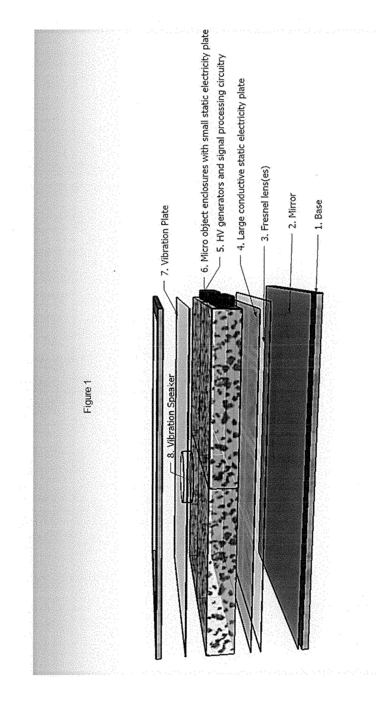
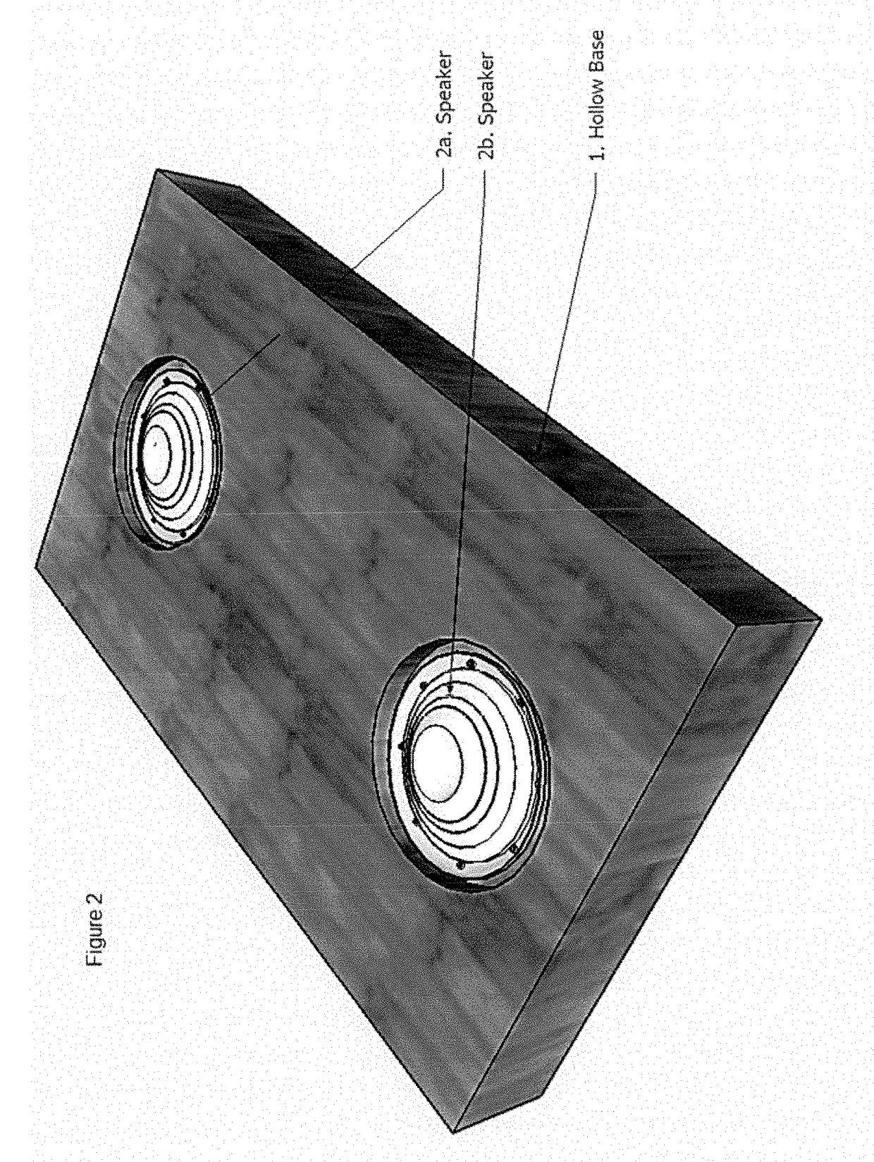
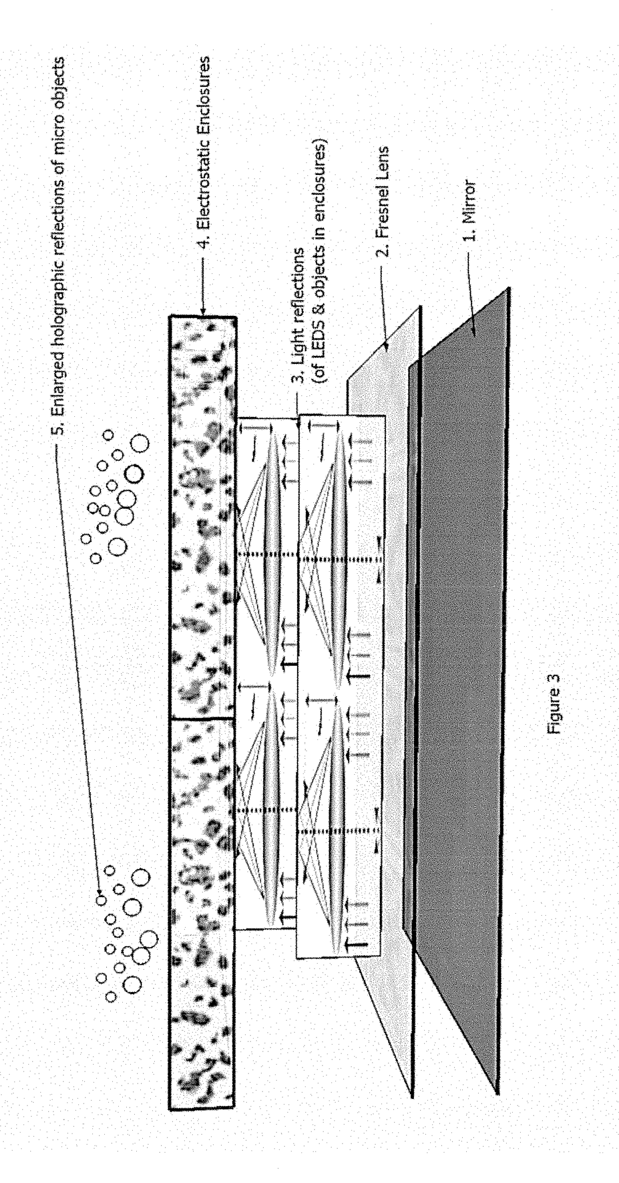
[0018]In a preferred embodiment, a mirror with possible dimensions 14″×20″ is placed inside at the base of a rectangular wooden box, with possible dimensions 15″×21″ which will serve as the display enclosure and speaker box. This mirror can be affixed with an adhesive such as epoxy resin which hardens and allows sound waves to be transmitted from the glass plate into the wood to produce a deeper, less metallic sound than just the mirror alone. A single rectangular fresnel lens of similar size is placed on top of the mirror or a combination of any number of smaller fresnel lenses can be arranged in a pattern, e.g, in one embodiment 4 individual lenses measuring 7″×10″ placed in a 2×2 grid can be utilized to produce a 3d-like, zoomed holographic projection of whatever is reflected by the mirror, the more lenses used the more reflections and holograms are produced.
[0019]The lens(es) can be affixed to the mirror using a transparent adhesive or glue at its edges or, as in this embodiment, 4 rectangular lenses are placed 2 inches above the mirror, mounted on swivel bearings which allow the lenses to swivel or partially rotate up and down moving in the vertical plane from about 0 to −30 degrees if the horizontal x-axis is considered 0 degree. To accomplish this, a rod serving as axle for the bearing is connected perpendicularly at the center along the length-side of each lens and connected with the rod facing toward the outer edges of the apparatus along its length also. The bearings are attached into the sides of the rectangular apparatus at approx 5″ and 15″ along both length sides at a height of approx 2″ above the mirror. At each width side of the apparatus placed approx 1″ above the mirror underneath each of the 4 fresnel lenses are placed 4 transparent conductive plates with dimensions 8″×2″ connected to the electrostatic sources. A conductive tape / strip is placed covering 1″ of the lenses at each width side and where the lenses are positioned to have their conductive strip directly above the conductive plates. When electrostatic energy is applied to the strip and the conductive plates below them the electromotive forces created move the lenses up and down on their swivels about the vertical plane. These movements are reminiscent of the input signal driving the electrostatic generators and cause light reflection changes and focal length changes which change the reflections through the lenses to somewhat match some of the changes in the input signal. Causing light to seemingly undulate or vibrate to the input and causing the holographic projections of objects and light to be distorted, enlarged and reduced based on the control signal.
[0020]Transparent rectangular cubes with conductive faces are connected electrostatic sources with wires in contact with an electrolyte placed in-between the double-plated transparent faces of each enclosure which contain objects and micro-spheres which move utilizing the electromotive or Coulomb force, or more specifically Coulomb Interactions controlled by the input signal. Utilizing a high voltage / low current electrostatic source to electrostatically charge and discharge one or more display cases containing lightweight micro-spheres or objects which may be of any shape. This is demonstrated when the charged light-weight objects jump up, down and in all other directions in a fully transparent display to the rhythm of the music or other audio if any is present or reflecting the intensity and fluctuations of more random signals using pulsed, controlled electrostatic discharges. The High Voltage sources used generated over 80 kV using low current( <10 mA) and were cycled on and off by circuitry controlled by the input electromagnetic signal. This signal is loaded into memory and reproduced by a IC controlled sound module via bluetooth or WiFi, amplified and run through low pass filters for cycling the HV sources with frequencies lower than 500 Hz as with, for example, the drum and kick instruments in music. With audio / music one enclosure handles left channel low frequency with larger objects and another left channel mid-low frequency with smaller objects. A 2×2 grid of electrostatic enclosures also represents the left and right channel of audio in this manner.

Problems solved by technology

The shortfall of all these methods and systems is that they don't display the sound in a three dimensional real world space and they don't display sounds in real time as they might be played in a multi-chord, multi-instrument song, for example.
They don't easily allow other methods of physically displaying signals to be incorporated because they are generally self contained systems in typically non transparent configurations.
These methods while capable of producing volumetric 3D displays which move objects pixel by pixel or location by location are slow, complex and not designed as consumer entertainment devices which reproduce and display signal patterns esp. sound, whereas this invention seeks to move objects, using electrostatic forces, to match any user inputted signal in order to show the signal itself, whether audible or not, instead of to show an image or moving image with preprogrammed pixel locations, as well as, allow the user to hear the signal simultaneously if desired.

Method used


Image

  • Visual Representation of Electromagnetic Signals Utilizing Controlled Electrostatic and Electromagnetic Vibration Energy within Transparent Conductive Enclosures
  • Visual Representation of Electromagnetic Signals Utilizing Controlled Electrostatic and Electromagnetic Vibration Energy within Transparent Conductive Enclosures
  • Visual Representation of Electromagnetic Signals Utilizing Controlled Electrostatic and Electromagnetic Vibration Energy within Transparent Conductive Enclosures

Examples


Embodiment Construction

[0038]This invention can be used as an audio receiver, speaker system, audio visual display, as a piece of display art, musical instrument or any combination of these applications where most functions of this apparatus including what audio or signal to input, intensity of display and light color / pattern selections can be controlled from a mobile device or computer via bluetooth or wifi or any other system which allows for similar connectivity. This invention can also be used as a scientific display apparatus which allows the viewer to specifically see not only the effects of sound waves and other electromagnetic signals on physical matter and the general cymatic geometry of soundwaves, thereby viewing the frequency response of a particular input signal but also the signal amplitude, rhythm and tempo using the effects of controlled static electricity, electromechanical vibrational energy on physical matter and the correlation and interplay between energy, light and matter in general....


PUM


Abstract

An apparatus and a method to facilitate the visual representation of electromagnetic signals, both audible and inaudible, which preferably is comprised of a component for realistically reproducing sound, if any, and necessarily is comprised of one or more components for producing a visual display which is influenced by inputted electromagnetic signals. This is achieved utilizing a high voltage/low current electrostatic source (charged above 10 kV) to electrostatically charge and discharge one or more display cases containing lightweight micro-spheres or objects of any shape or size capable of being influenced by electrostatic energy. This is demonstrated when the charged light-weight objects jump up, down and in all other directions in a fully transparent display to the rhythm of the music or other audio if any is present or reflecting the amplitude, intensity and frequency fluctuations of more random signals using pulsed, controlled electrostatic discharges. These characteristics are also shown by light displays which sway and waver with the electrostatic discharges and which flash with various signal changes. These characteristics are further demonstrated by micro-bead substrate changes which occur with vibrations of a transparent vibration plate. Various lenses, mirrors and even the lights within the system can also be made to move with the signal using the method described by this invention to change, light strip position, light reflection angles, focal points and magnification. Furthermore reflections of lights and the moving objects in the transparent electrostatic display enclosures are projected in a three dimensional visualization above the top display window of the apparatus utilizing fresnel lenses and a reflective mirror system as they move and sway, their movements, undulations, and reflections are projected and magnified, along with the movements of the objects for the viewer/user's entertainment. Achieving these results involves a method of making electrically conductive sheets and apparatus layers which are almost completely transparent so as to not impede the passage of light through the apparatus, also utilization of a transparent vibration plate and micro-beads with desired properties.

Description

FIELD OF INVENTION[0001]The present invention relates to arrangements for making visible or audible the words spoken. Specifically describing a means of radiating and simultaneously displaying combined wave patterns and other characteristics of both audible and inaudible signals, especially resonant standing wave nodes, antinodes, amplitude, rhythm and frequency changes in a dynamic, three dimensional visualization system of light, object and particulate displays utilizing electromechanical vibration energy, light and electrostatic energy controlled by an input signal.BACKGROUND OF INVENTION[0002]The use of speaker systems has been a long standing method of listening to audio in all formats. Many people also use light displays with mostly LEDs and lasers which flash to the changing tones of the audio or rhythm of the music being played especially in homes, nightclubs or enclosed in vehicle based speaker box systems. Some other variations in light patterns, e.g. LED equalizers on hom...

Claims


Application Information

Patent Timeline
Patent Type & Authority Applications(United States)
IPC IPC(8): G09G3/34G09G3/00
CPCG09G3/3433G09G3/003G09G2300/0469G10H3/12G10H1/0008G10L21/10G09G3/346G10H2220/005
Inventor MITCHELL, SOWETO ABIJAH
Owner MITCHELL SOWETO ABIJAH
Why Eureka
Try Eureka