Insulated joystick assembly

a joystick and assembly technology, applied in the field of joysticks, can solve the problems of increasing not being convenient to use the boom cover, and the operator of the boom is in danger of electric shock, so as to reduce the number of components needed, reduce the risk of electric shock, and be more reliable

Active Publication Date: 2019-02-28
ALTEC INDS
View PDF13 Cites 5 Cited by
  • Summary
  • Abstract
  • Description
  • Claims
  • Application Information

AI Technical Summary

Benefits of technology

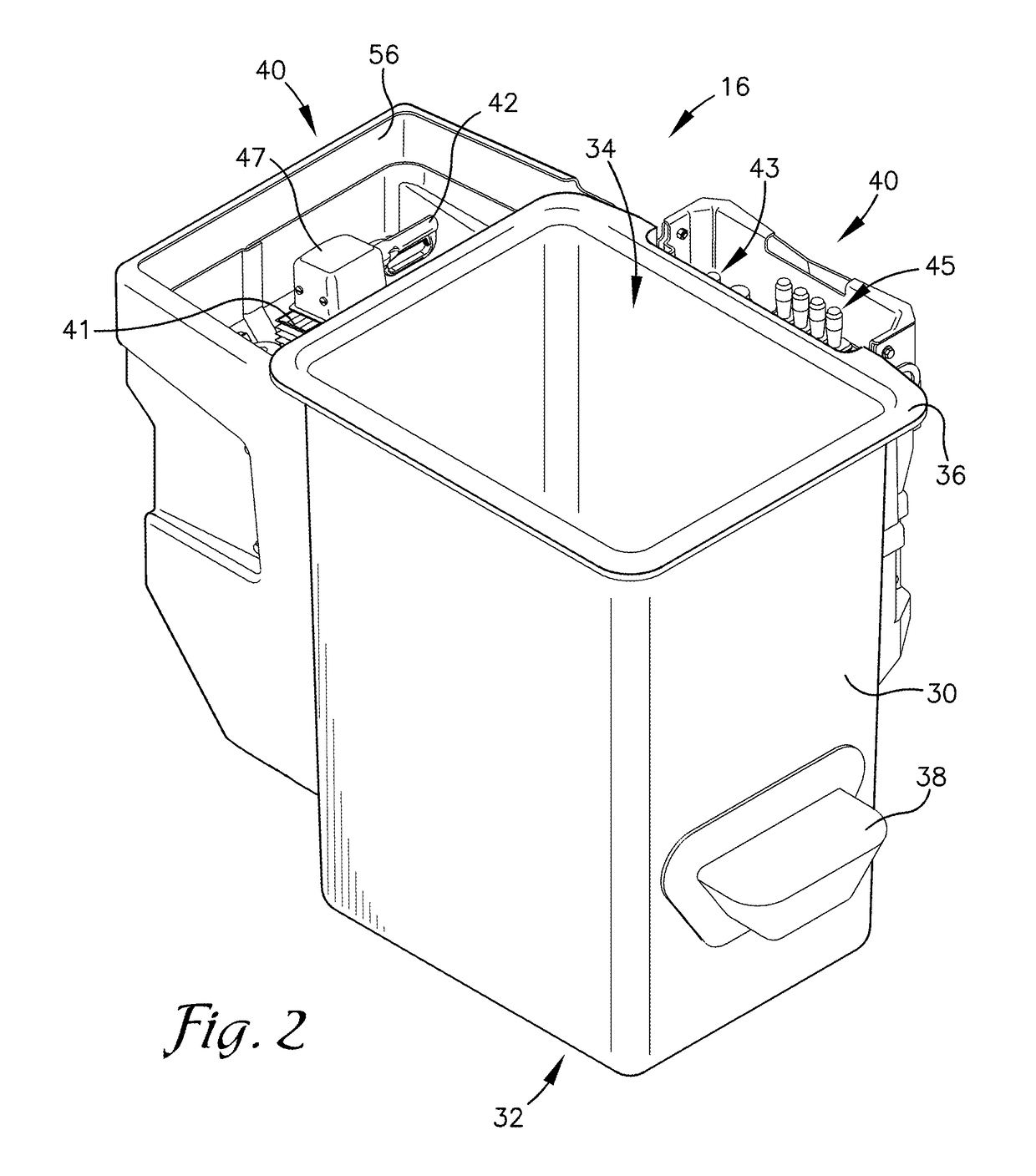
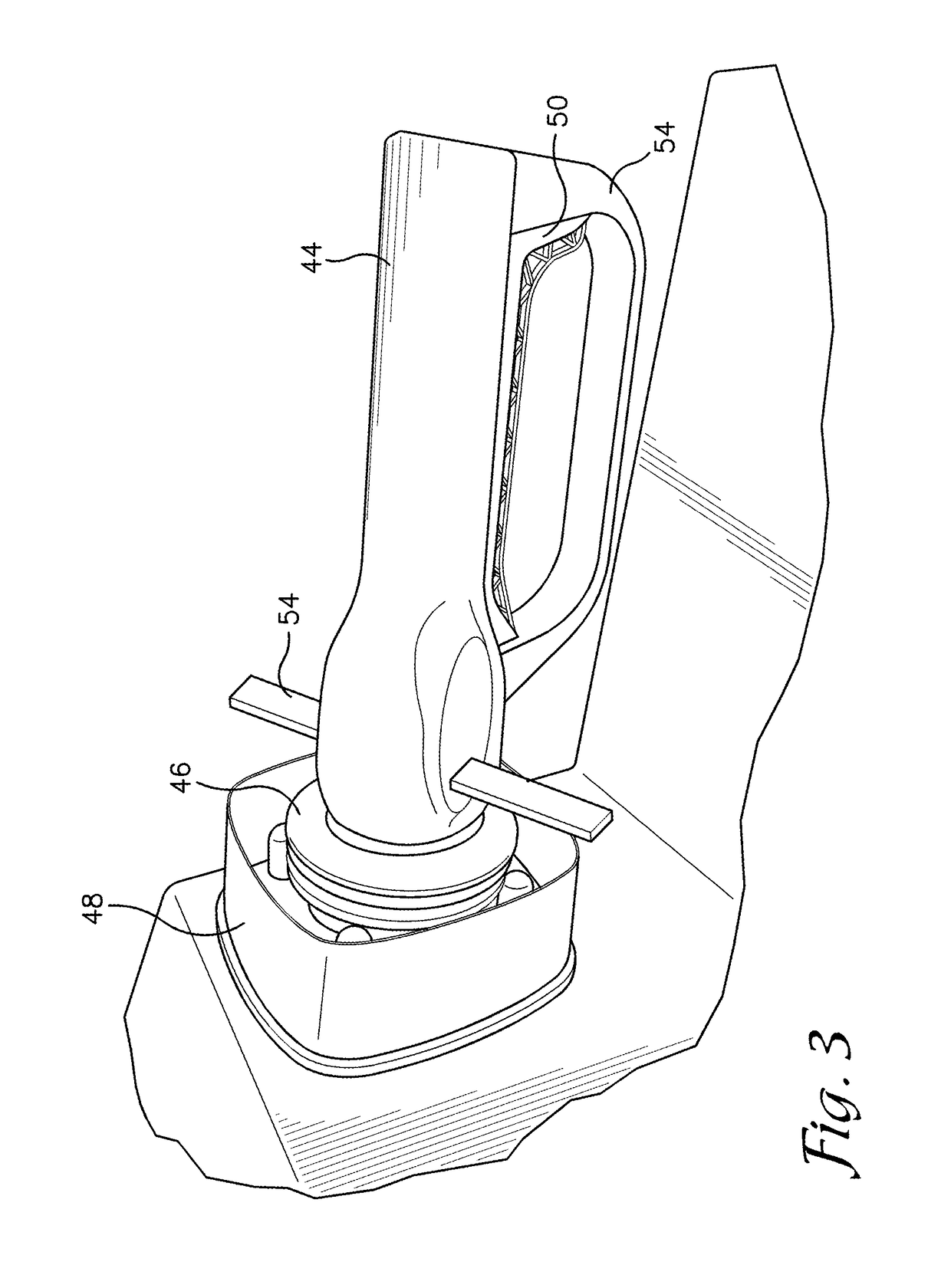
[0005]Embodiments of the invention solve these problems by providing layers of insulation between electronic components and an operator. A handle utilized by the operator may be formed of, or at least one surface coated or covered in, a highly-resistant material. A highly-resistant material is a material that is resistant to the flow of electricity, such as fiberglass, silicon, porcelain, glass, rubber, and non-conductive polymers. The highly-resistant material may also extend to other components such as a connecting rod and a mounting base. This may separate the operator from electrically charged components. As well as separating the operator the rod may be received at the base by force measuring sensors. This allows the handle and rod to remain stationary and only the applied force to be measured, thus decreasing the number of components needed in the assembly. By decreasing the number of components, the assembly may be more reliable and less expensive.

Problems solved by technology

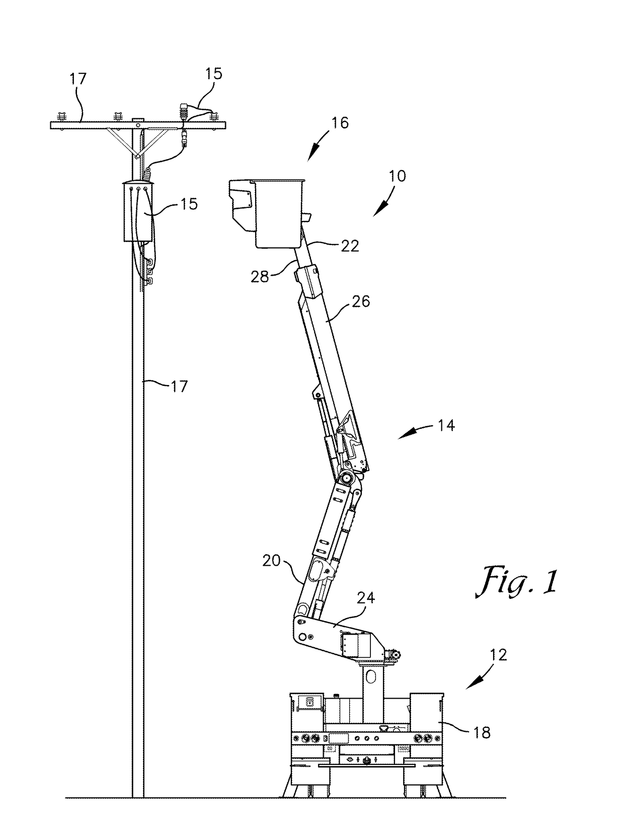
A boom truck performing utility work may be in danger of contacting electrified components thus electrifying the boom.
When this occurs, the operator of the boom is in danger of electric shock.
However, these are not always reliable and they may become damaged, increasing the risk of electric shock.
It also may not be convenient to use boom covers and alternative insulation methods may be needed.
Other problems with joystick type controller systems are the amount of moving parts and the difficulty of operation for an operator.
Complex moving parts cause reliability issues, wear on components, and high repair costs.
The current controllers may require large actuations before the boom responds and may have high levels of deadband causing reduced feedback and accuracy when operating a boom.

Method used


Image

  • Insulated joystick assembly
  • Insulated joystick assembly
  • Insulated joystick assembly

Examples


Embodiment Construction

[0019]The following detailed description references the accompanying drawings that illustrate specific embodiments in which the invention can be practiced. The embodiments are intended to describe aspects of the invention in sufficient detail to enable those skilled in the art to practice the invention. Other embodiments can be utilized and changes can be made without departing from the scope of the invention. The following detailed description is, therefore, not to be taken in a limiting sense. The scope of the invention is defined only by the appended claims, along with the full scope of equivalents to which such claims are entitled.

[0020]In this description, references to “one embodiment,”“an embodiment,” or “embodiments” mean that the feature or features being referred to are included in at least one embodiment of the technology. Separate references to “one embodiment,”“an embodiment,” or “embodiments” in this description do not necessarily refer to the same embodiment and are a...


PUM

PropertyMeasurementUnit
displacementaaaaaaaaaa
electrically highly-resistantaaaaaaaaaa
non-conductiveaaaaaaaaaa

Abstract

A joystick assembly is disclosed. In embodiments, the joystick controls a boom and aids in insulating a user from potential electric shock. Handle utilized by the operator may be made of, or at least one surface coated or covered in, material highly-resistant to electric current. The highly-resistant material may also extend to other components such as, a connecting rod, and a mounting base. The highly-resistant components may separate the operator from electrically charged components. As well as separating the operator from potentially electrically charged components, the rod may be received at the base by force measuring sensors, or strain measuring sensors may be attached to the rod. This allows the handle and rod to be stationary and, in embodiments, rigid, and only the applied force to be measured, thus decreasing the number of components needed in the assembly.

Description

BACKGROUND1. Field[0001]Embodiments of the invention are broadly directed to electrical insulation of a user input device. More specifically embodiments of the invention relate to a joystick that may comprise electrically highly-resistant material providing layers of insulation between a machine operator and electrically energized machine components.2. Related Art[0002]Controlling the movement of a boom and a utility bucket is performed by an operator in the utility bucket using a single handle controller, or joystick. A boom truck performing utility work may be in danger of contacting electrified components thus electrifying the boom. When this occurs, the operator of the boom is in danger of electric shock. Boom covers, that may be dielectric, are commonly used to prevent boom components from coming in direct contact with energized conductors. However, these are not always reliable and they may become damaged, increasing the risk of electric shock. Levels of redundancy should be e...

Claims


Application Information

Patent Timeline
Patent Type & Authority Applications(United States)
IPC IPC(8): H01B17/00
CPCH01B17/005H01B17/64G05G9/04737B66F11/046H02B3/00H02B5/02G05G1/06G05G9/047
Inventor GORGHUBER, STEVEN J.HESLEY, MITCHELL D.
Owner ALTEC INDS
Why Eureka
Try Eureka