Patch array antenna, directivity control method therefor and wireless device using patch array antenna

a technology of directivity control and antenna, which is applied in the direction of antennas, individually energised antenna arrays, electrical appliances, etc., can solve the problems of increasing the size of the rf circuit, increasing the cost of the antenna, and low durability of the dielectric phase shifter, so as to achieve low cost, increase the number of active components, and high durability

Active Publication Date: 2019-02-28
NEC CORP
View PDF0 Cites 16 Cited by
  • Summary
  • Abstract
  • Description
  • Claims
  • Application Information

AI Technical Summary

Benefits of technology

[0071]According to the present invention, it is possible to provide a patch array antenna being capable of electrically controlling directivity, and having...

Problems solved by technology

Therefore, in the methods described above, there is a disadvantage that a circuit size of an RF circuit increases.
Therefore, in the methods of PTLs 4 to 6, there is a disadvantage that, when a high directivity gain is intended to be obtained by increasing the number of antenna elements, a cost of an antenna ...

Method used


Image

  • Patch array antenna, directivity control method therefor and wireless device  using patch array antenna
  • Patch array antenna, directivity control method therefor and wireless device  using patch array antenna
  • Patch array antenna, directivity control method therefor and wireless device  using patch array antenna

Examples


examples

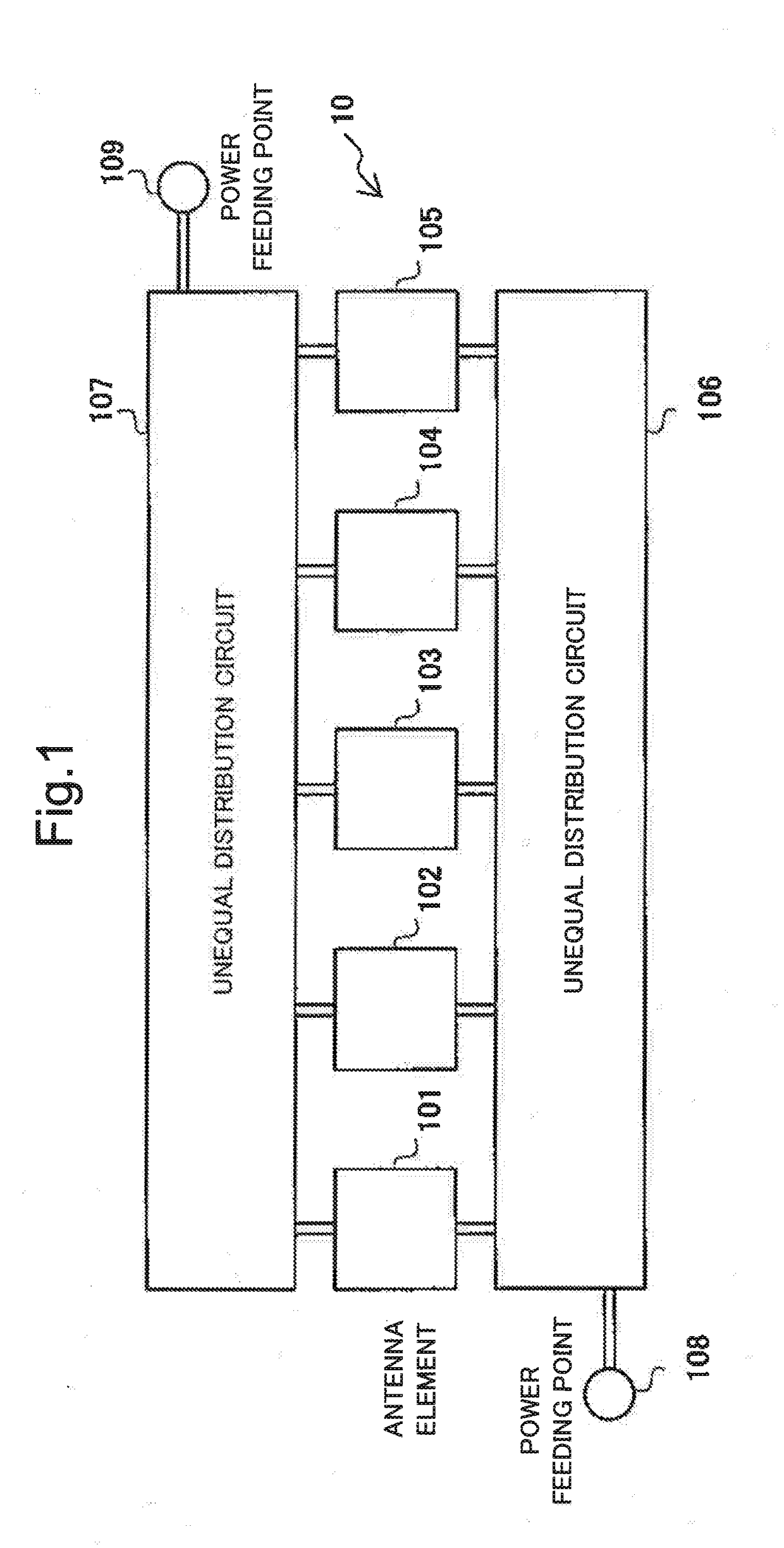
[0123]FIG. 12 illustrates a first example of the patch array antenna according to the present invention. A patch array antenna 120 thereof includes a pattern in which each of first and second unequal distribution circuits 1206 and 1207 is illustrated in a frame indicated by a dotted line. In the first unequal distribution circuit 1206, a wiring distance of a first microstrip line from a first power feeding point 1208 to first to fourth antenna elements 1201 to 1204 that are feeding targets is constant. Similarly, in the second unequal distribution circuit 1207, a wiring distance of a second microstrip line from a second power feeding point 1209 to second to fifth antenna elements 1202 to 1205 that are feeding targets is constant. In the first and second unequal distribution circuits 1206 and 1207, in order to match impedances and achieve first and second distribution ratios determined, patterns of the first and second microstrip lines are formed as follows.

[0124]A distribution ratio...


PUM


Abstract

To provide a patch array antenna that allows a limited increase in active component even if the number of antenna elements increases, in a first unequal distribution circuit 106, a first distribution ratio of the power of a first high-frequency signal to be distributed from a first feeding point 108 to first to Nth antenna elements is set to be one of monotone increasing and monotone decreasing with respect to a row of the first to Nth antenna elements. In a second unequal distribution circuit 107, a second distribution ratio of the power of a second high-frequency signal to be distributed from a second feeding point 109 to the first to Nth antenna elements is set to be the other of monotone increasing and monotone decreasing with respect to the row of the first to Nth antenna elements. Directivity is controlled by changing a phase difference between the first and second high-frequency signals.

Description

TECHNICAL FIELD[0001]The present invention relates to a patch array antenna, a directivity control method therefor, a wireless device using a patch array antenna, and a two-dimensional array antenna.BACKGROUND ART[0002]As one type of an antenna used in a high-frequency band equal to or more than a microwave, there is a patch antenna.[0003]The patch antenna is referred to also as a microstrip antenna and is a generic term for antennas formed by using a conductor subjected to printed wiring on a dielectric substrate. The patch antenna features low production cost.[0004]An antenna in which high directivity is produced by arranging a plurality of antenna elements on a planar surface is specifically referred to as a patch array antenna among various types of patch antennas. In a patch array antenna, a signal having a phase or an amplitude different for each antenna element thereof is provided, and thereby directivity can be changed. Therefore, a patch array antenna is often used for mili...

Claims


Application Information

Patent Timeline
IPC IPC(8): H01Q3/26H01Q21/06
CPCH01Q3/26H01Q21/065H01Q3/36H01Q21/22
Inventor IGURA, HIROYUKI
Owner NEC CORP
Why Eureka
Try Eureka