Illumination apparatus comprising plural light emitting units, control method therefor, illumination system, and image pickup apparatus

a technology of light emitting units and illumination systems, applied in the direction of television systems, instruments, color signal processing circuits, etc., can solve the problems of difficulty in adjusting the light amount, mismatch of white balances, and photographer's omission of shutter chances

Inactive Publication Date: 2019-02-28
CANON KK
View PDF4 Cites 0 Cited by
  • Summary
  • Abstract
  • Description
  • Claims
  • Application Information

AI Technical Summary

Benefits of technology

[0009]The present invention provides an illumination apparatus which is capable of suppressing a mismatch between color temperature information for each of a plurality of light emitting units, a control method therefor, an illumination system, and an image pickup apparatus.

Problems solved by technology

For this reason, when a white balance is decided according to the color temperature information in the image pickup apparatus, a mismatch can occur in white balances decided for each pieces of color temperature information.
For this reason, when shooting is performed with the illumination apparatus, a photographer may miss a shutter chance.
In addition, in terms of making the color temperature information for each of illumination apparatuses the same, the charging voltage and the light emission amount for the plurality of illumination apparatus are defined, which makes an adjustment of the light amount difficult.

Method used


Image

  • Illumination apparatus comprising plural light emitting units, control method therefor, illumination system, and image pickup apparatus
  • Illumination apparatus comprising plural light emitting units, control method therefor, illumination system, and image pickup apparatus
  • Illumination apparatus comprising plural light emitting units, control method therefor, illumination system, and image pickup apparatus

Examples


first embodiment

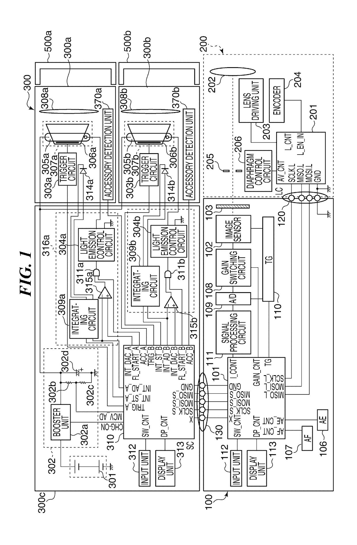
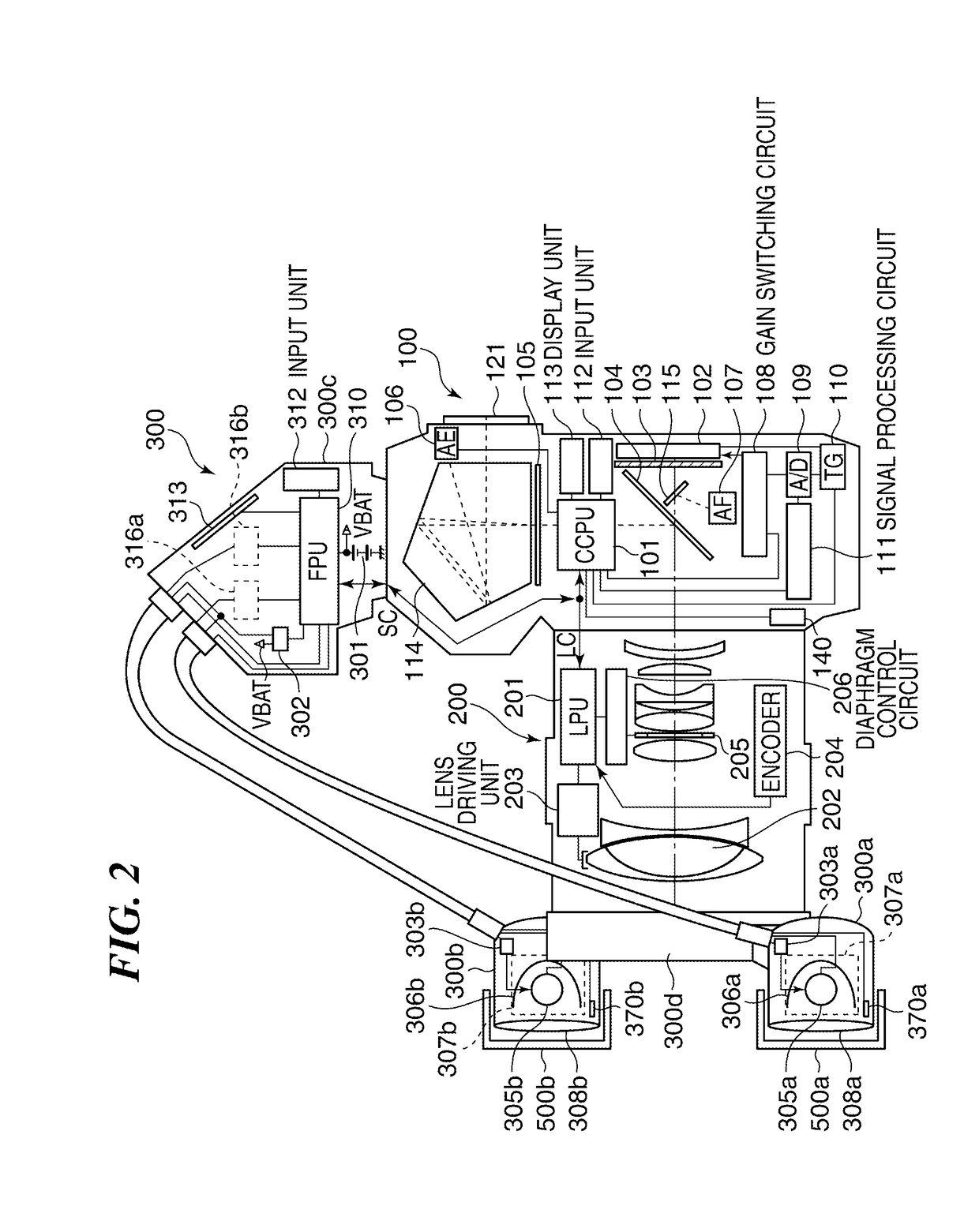
[0024]FIG. 1 is a view showing an arrangement of an example of an image pickup apparatus comprising an illumination apparatus according to the present invention. FIG. 2 is a view showing an arrangement of the image pickup apparatus appearing in FIG. 1 with a part of it being raptured.

[0025]Referring to FIGS. 1 and 2, the image pickup apparatus shown in the figure is, for example, a digital camera (hereinafter merely referred to as a camera) having a camera main body 100. An interchangeable shooting lens unit (shooting optical system: hereinafter, merely referred to as a shooting lens) 200 is attached to the camera main body 100. A detachably attachable illumination apparatus (flash apparatus: hereinafter, merely referred to as a flash) 300 is attached to the camera main body 100.

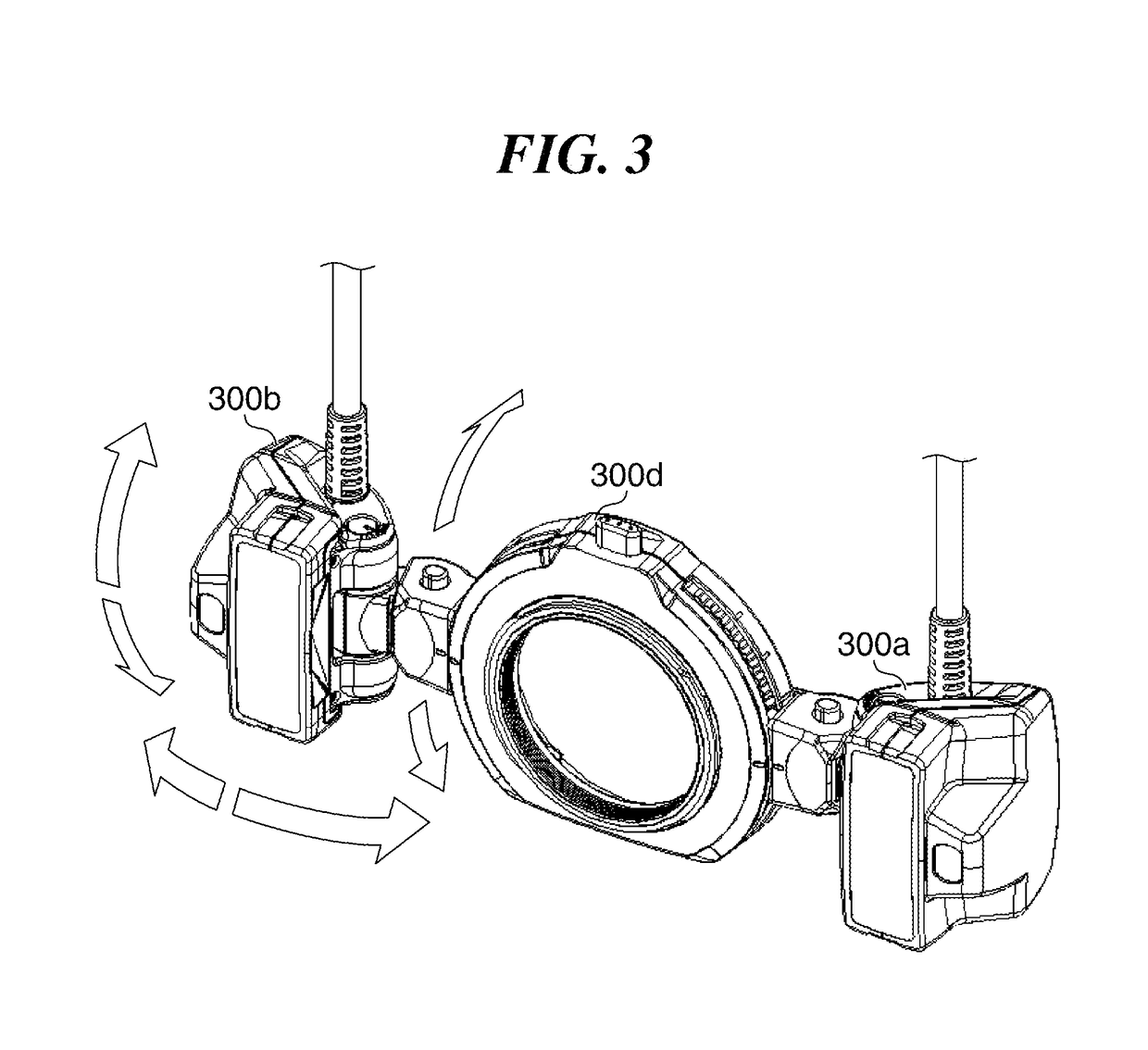
[0026]The flash 300 has a first light emitting unit 300a and a second light emitting unit 300b. The first light emitting unit 300a and the second light emitting unit 300b are detachably attached to a ring un...

second embodiment

[0102]Next, a description will be given of an example of a camera comprising a flash according to the present invention.

[0103]FIG. 6 is a view showing an arrangement of the camera comprising the flash according to the second embodiment of the present invention. It should be noted that in FIG. 6, the same reference numerals are assigned to the same component elements as that of the camera in FIG. 1, and explanations thereof are omitted.

[0104]As shown in the figure, the first light emitting unit 300a and the second light emitting unit 300b have a first bounce detection unit 371a and a second bounce detection unit 371b, respectively. The first bounce detection unit 371a and the second bounce detection unit 371b each detects whether an irradiation direction of the first light emitting unit 300a or the second light emitting unit 300b has changed from a predetermined normal position. That is, the first bounce detection unit 371a and the second bounce detection unit 371b each detects wheth...

third embodiment

[0115]Subsequently, a description will be given of an example of a camera comprising a flash according to the present invention.

[0116]FIG. 7 is a view showing an arrangement of the example of the camera comprising the flash according to the third embodiment of the present invention. It should be noted that in FIG. 7, the same reference numerals are assigned to the same component elements as that of the camera in FIG. 1, and explanations thereof are omitted.

[0117]As shown in the figure, the first light emitting unit 300a and the second light emitting unit 300b have a first distance measurement unit 372a and a second distance measurement unit 372b, respectively. The first distance measurement unit 372a and the second distance measurement unit 372b measure a distance from the first light emitting unit 300a to the subject and a distance from the second light emitting unit 300b to the subject, respectively. In the example shown in the figure, the first distance measurement unit 372a and ...


PUM


Abstract

An illumination apparatus which is capable of suppressing a mismatch between color temperature information for each of a plurality of light emitting units that illuminate a subject with light. Whether an optical accessory for toning or adjusting a light distribution angle is attached is detected for each of the plurality of light emitting units. The color temperature information indicative of a color temperature in a light emission when the plurality of light emitting units are caused to emit the light is decided according to light emission information indicative of a light emission state in each of the plurality of light emitting units and a detection result.

Description

BACKGROUND OF THE INVENTIONField of the Invention[0001]The present invention relates to an illumination apparatus, a control method therefor, an illumination system, and an image pickup apparatus, and in particular to an illumination apparatus comprising a plurality of light emitting units.Description of the Related Art[0002]In general, an illumination apparatus used together with an image pickup apparatus such as a digital camera sends color temperature information of a light at a time of light emission to the image pickup apparatus, which in turn performs a white balance adjustment based on the color temperature information.[0003]FIG. 10 is a perspective view showing an example of a conventional illumination apparatus.[0004]The illumination apparatus 1000 shown in the figure is a so-called normal illumination apparatus of clip-on type which is detachably attachable to an image pickup apparatus (not shown) and has one light emitting unit 1001. Since the illumination apparatus 1000 ...

Claims


Application Information

Patent Timeline
Patent Type & Authority Applications(United States)
IPC IPC(8): H04N5/225H04N5/235G06T7/521H04N9/73G03B15/05
CPCH04N5/2256H04N5/2351G06T7/521H04N9/735G03B15/05G03B2215/0596H04N23/56H04N23/60H04N23/74H04N23/10H04N23/88G03B2215/0553G03B2215/056G03B2215/05H04N23/71
Inventor SAITO, KEIICHIRO
Owner CANON KK
Why Eureka
Try Eureka