Brake disk and method for manufacturing the same

Inactive Publication Date: 2019-03-07
HYUNDAI MOTOR CO LTD +1
View PDF1 Cites 0 Cited by
  • Summary
  • Abstract
  • Description
  • Claims
  • Application Information

AI Technical Summary

Benefits of technology

[0018]A brake disk manufactured by the methods according to the present invention may reduce a judder phenomenon by reducing a maximum BTV through a relatively simple process, and improve motional quality

Problems solved by technology

However, when the brake torque increased during the braking does not maintain a constant level, but vibrates while

Method used


Image

  • Brake disk and method for manufacturing the same
  • Brake disk and method for manufacturing the same
  • Brake disk and method for manufacturing the same

Examples


Example

[0027]The terminology used herein is merely for mentioning a specific embodiment, and is not intended to limit the present invention. A singular form used herein includes a plural form as long as the word does not indicate obviously the opposite meaning. The term “include” used in the specification specifies specific characteristics, an area, an essence, a step, an operation, an element, and / or a component, and does not exclude existence or addition of other specific characteristics, an area, an essence, a step, an operation, an element, a component and / or a group.

[0028]It is understood that the term “vehicle” or “vehicular” or other similar term as used herein is inclusive of motor vehicles in general such as passenger automobiles including sports utility vehicles (SUV), buses, trucks, various commercial vehicles, watercraft including a variety of boats and ships, aircraft, and the like, and includes hybrid vehicles, electric vehicles, plug-in hybrid electric vehicles, hydrogen-pow...


PUM

PropertyMeasurementUnit
Fractionaaaaaaaaaa
Thicknessaaaaaaaaaa
Thicknessaaaaaaaaaa

Abstract

Disclosed are a brake disk and a method for manufacturing the same. In particular, the brake disk may include a friction surface formed of cast iron, and the friction surface of the brake disk is divided into a plurality of sections in a circumferential direction. Preferably, an average of the numbers per unit area of eutectic cells formed on surfaces of the sections may not be greater than 300 ea/cm2.

Description

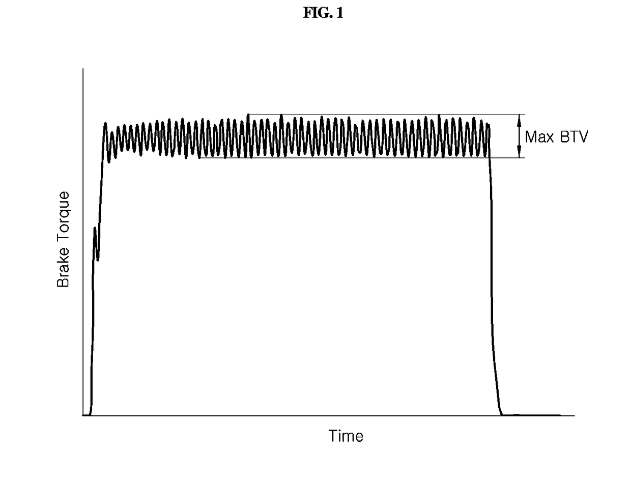
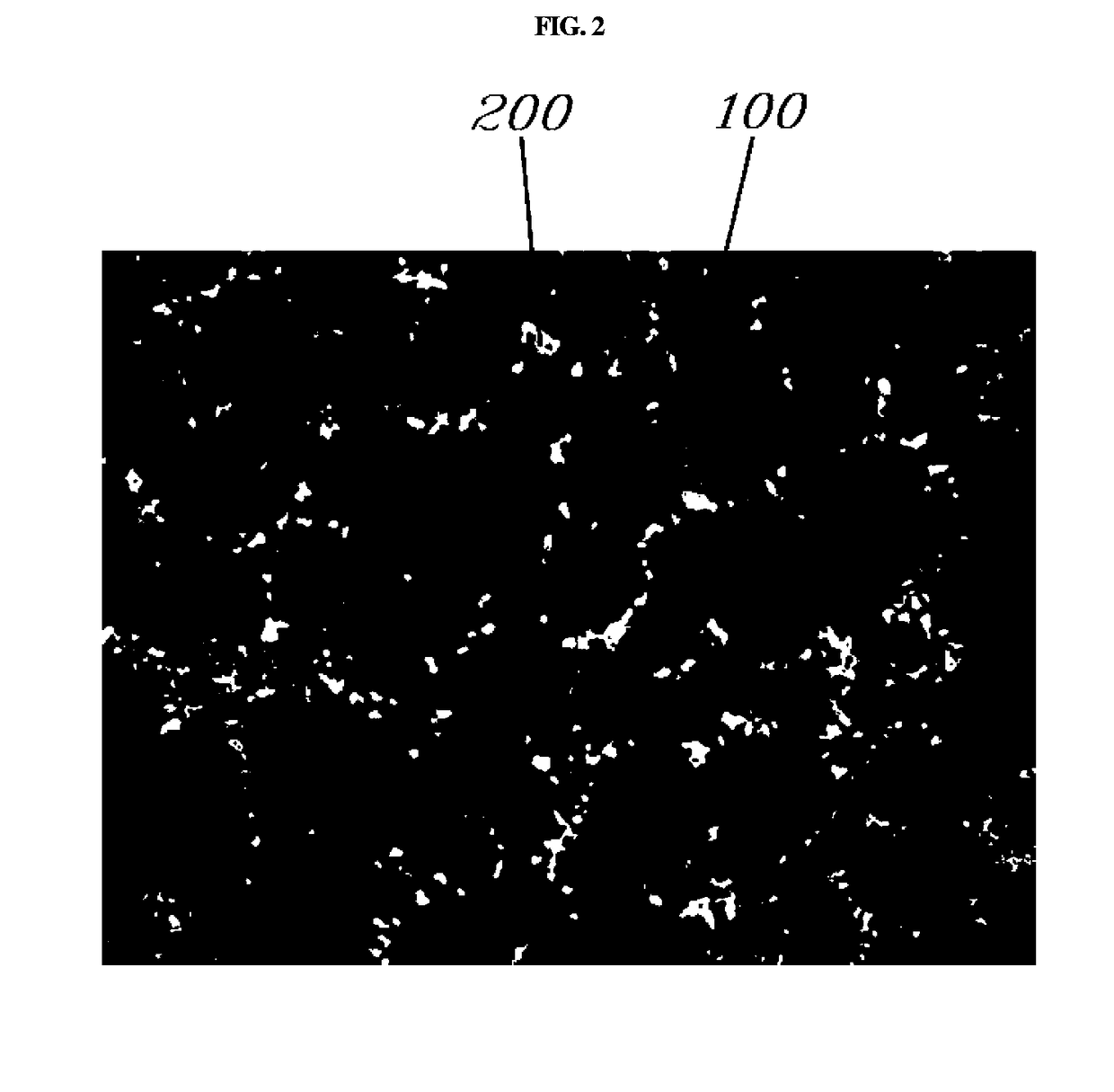
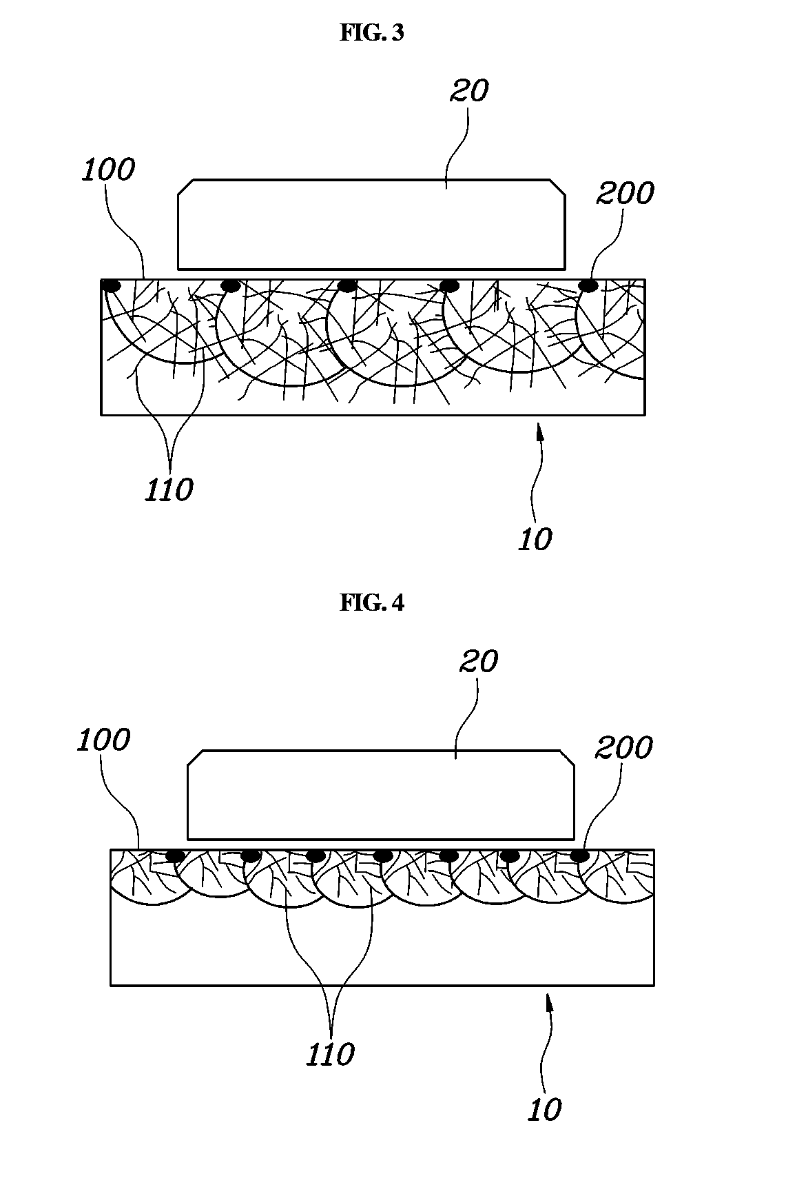
CROSS REFERENCE TO RELATED APPLICATION[0001]The present application claims priority of Korean Patent Application No. 10-2017-0113501 filed on Sep. 5, 2017, the entire contents of which is incorporated herein for all purposes by this reference.TECHNICAL FIELD[0002]The present invention relates to a brake disk including a friction surface formed of cast iron and a method for manufacturing the same.BACKGROUND OF THE INVENTION[0003]When a brake is used to brake a driving vehicle, the speed of the vehicle decreases as a brake torque increases. However, when the brake torque increased during the braking does not maintain a constant level, but vibrates while repeatedly increasing / decreasing, a judder phenomenon occurs in which such vibration is transferred to a passenger.[0004]FIG. 1 illustrates a vibration phenomenon of a brake torque during braking, which may result in the judder phenomenon. A maximum brake torque vibration (BTV) is defined as a height difference between an uppermost end...

Claims


Application Information

Patent Timeline
IPC IPC(8): F16D65/12F16D65/00
CPCF16D65/127F16D65/0006F16D2065/1312F16D2200/0013F16D2250/0007F16D2250/003B22D15/00B24B19/00F16D65/12F16D65/125F16D65/02B24B7/17F16D2065/1316
Inventor CHUNG, MIN GYUNHAN, JAI MINRHEE, YOON JOOLEE, BYUNG CHANLEE, JAE YOUNGKIM, YOON CHEOL
Owner HYUNDAI MOTOR CO LTD
Why Eureka
Try Eureka