Salt Bath Ferritic Nitrocarburizing of Brake Rotors

a technology of ferritic nitrocarburizing and brake rotors, which is applied in the direction of heat treatment apparatus, brake discs, manufacturing tools, etc., can solve the problems of surface corrosion, pedal pulsation or a corroded braking surface, high temperatures on the rotor cheek surfaces, etc., and achieve the absence of distortion of the case structure and provide oxidation resistance.

Active Publication Date: 2008-01-03
KOLENE +1
View PDF10 Cites 46 Cited by
  • Summary
  • Abstract
  • Description
  • Claims
  • Application Information

AI Technical Summary

Benefits of technology

[0009]The present invention is a means for producing a ferritic nitrocarburized surface treatment of cast iron brake rotors to thereby provide oxidation resistance and an absence of distortion to the case structure.

Problems solved by technology

The normal course of operation of a brake system involves production of high levels of friction, which, in turn, generates high temperatures on the rotor cheek surfaces.
Environmental effects caused by exposure to corrosive agents, such as road salt and water, exacerbate these problems.
These effects, either singly or in combination, can result in pedal pulsation or a corroded braking surface.
Surface corrosion that would normally be inconsequential in the operation of the braking system becomes an issue due to the perception of this oxidation.
Ceramic coatings and metallic plates provide corrosion protection, however, these have negative, undesirable braking characteristics.
However, this process may produce geometric distortions that are problematic.
Additionally, gaseous ferritic nitrocarburizing may involve long cycle times. Case hardening techniques such as conventional carbonitriding as performed above a critical temperature of the ferrous material, can result in very high distortion, long cycle times and a case structure that is not optimized for corrosion performance.

Method used


Image

  • Salt Bath Ferritic Nitrocarburizing of Brake Rotors
  • Salt Bath Ferritic Nitrocarburizing of Brake Rotors
  • Salt Bath Ferritic Nitrocarburizing of Brake Rotors

Examples


Embodiment Construction

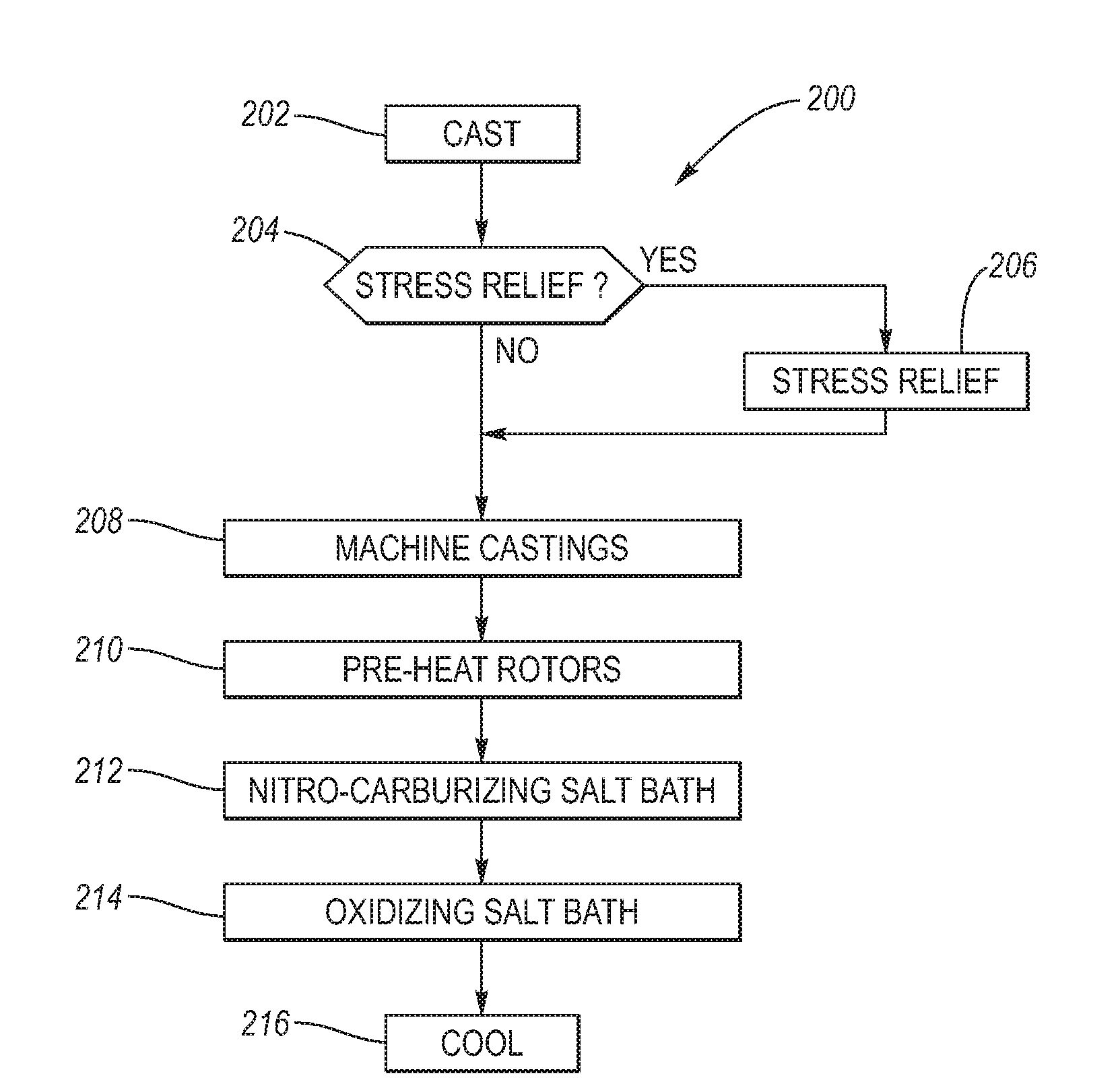
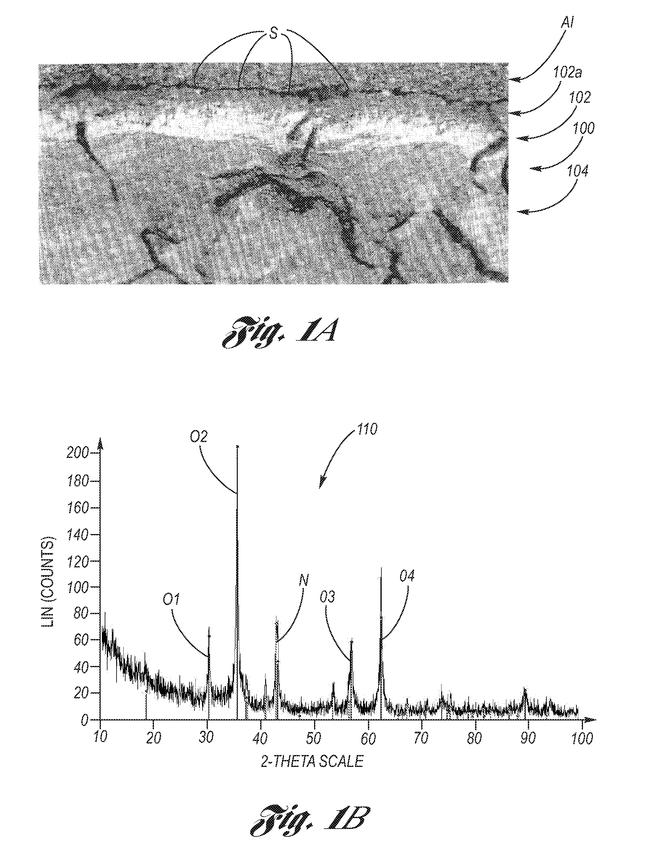
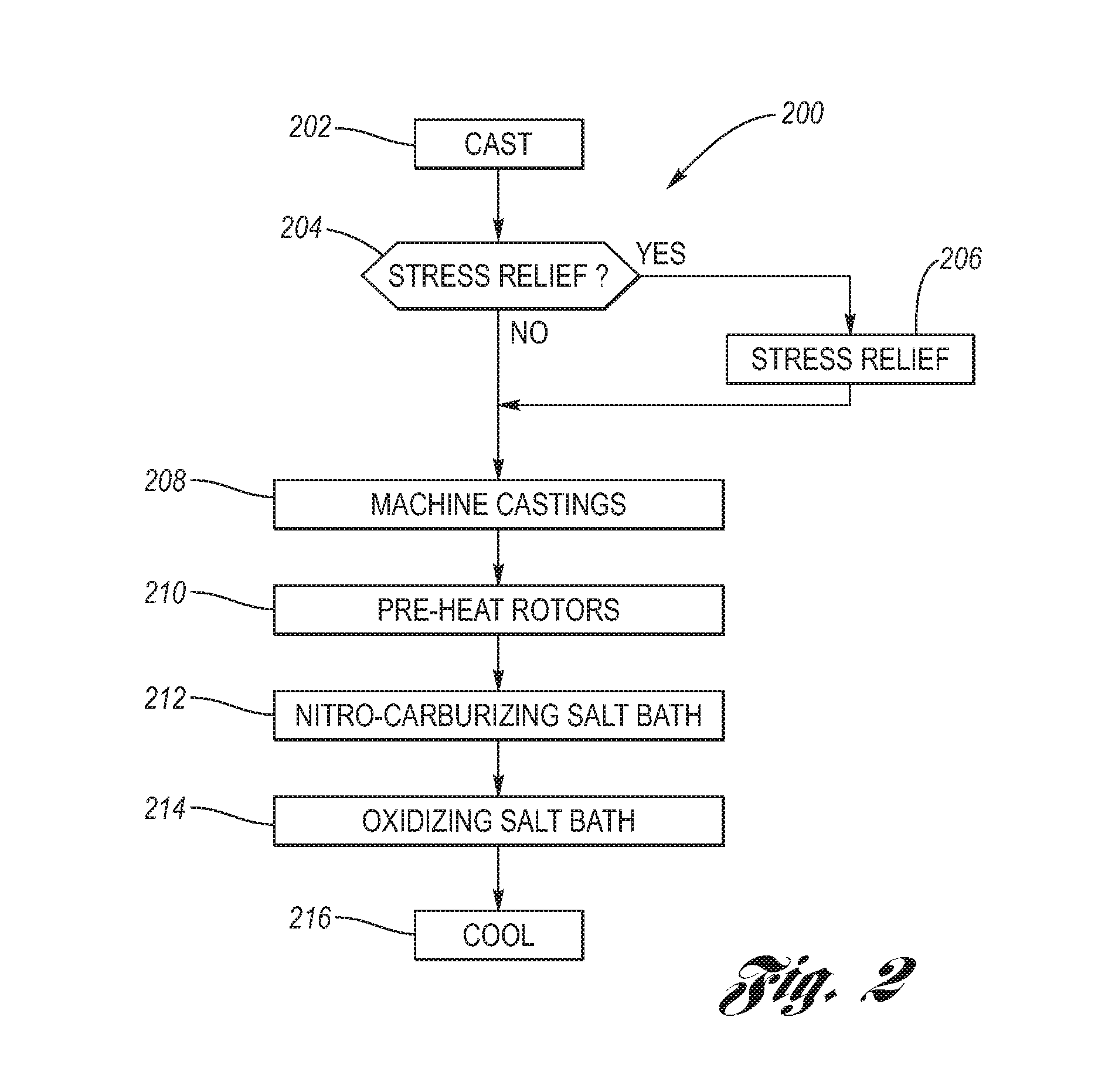
[0027]Referring now to the Drawing, FIGS. 1A through 5 depict an example of a two salt bath ferritic nitrocarburizing system (process and apparatus) for producing a ferritic nitrocarburized surface treatment of cast iron brake rotors. The following description of the preferred embodiments is merely exemplary in nature and is not intended to limit the invention, its applications, or its uses.

[0028]FIG. 1A shows a cross-section of the surface microstructure of a ferrous material 100, a pearlitic cast iron brake rotor, subjected to the salt bath ferritic nitrocarburizing process according to the present invention. This process initially introduces carbon and nitrogen simultaneously from a nitrocarburizing salt bath into the surface S of the ferrous material 100 (an aluminum foil A1 which is shown is merely an artifact of the testing set-up, and it does not form a part of the ferrous material 100). Thereafter, the ferrous material 100 is treated in an oxidizing salt bath. This step of t...


PUM

PropertyMeasurementUnit
depthaaaaaaaaaa
depthaaaaaaaaaa
temperatureaaaaaaaaaa

Abstract

Ferritic nitrocarburized surface treatment of cast iron brake rotors providing oxidation resistance, good braking performance and absence of distortion. Machined brake rotors are pre-heated, then immersed into a high temperature molten nitrocarburizing salt bath for a first predetermined dwell time. After removing the brake rotors from the nitrocarburizing salt bath, the brake rotors are directly immersed into an oxidizing salt bath at a lower temperature than the nitrocarburizing salt bath so that the brake rotors are thermally quenched. After a predetermined second dwell time in the oxidizing salt bath, the brake rotors are removed therefrom and further cooled to room temperature, either by water application thermal quenching or slow cooling in air. A fixture provides stable holding the brake rotors with a minimum of contact during placement in the salt baths.

Description

TECHNICAL FIELD[0001]The present invention relates to the treatment of the surface of cast iron brake rotors to improve performance characteristics, and more particularly to the nitrocarburizing of the surface of cast iron brake rotors to mitigate the effects of rotor surface oxidation and corrosion.BACKGROUND OF THE INVENTION[0002]The brake rotor is an integral component of braking systems across multiple types of motor vehicles. The disc brake is an energy conversion device which converts mechanical energy to heat. Disc braking systems consist of a non-rotating friction material and application sub-systems, as well as a brake rotor that rotates with the wheel. To stop or slow the vehicle, the friction material sub-system is engaged with the braking surfaces (rotor cheeks) of the brake rotor to generate heat due to friction, thereby converting mechanical energy to heat, and thereby slowing the rotation of the wheel.[0003]The performance of the braking system, in general, and the br...

Claims


Application Information

Patent Timeline
Patent Type & Authority Applications(United States)
IPC IPC(8): C23C8/32
CPCC21D1/607C23C8/58F16D65/12F16D69/02F16D65/127F16D2250/0046F16D2250/0053F16D65/125F16D2250/0038
Inventor HOLLY, MICHAEL L.REED, DOUGLAS N.EASTERDAY, JAMES R.
Owner KOLENE
Why Eureka
Try Eureka