High-Temperature Superconducting Coil Having Smart Insulation, High-Temperature Superconducting Wire Used Therefor, and Manufacturing Method Therefor

a superconducting coil and high-temperature technology, applied in the direction of superconductors/hyperconductors, superconducting magnets/coils, magnetic bodies, etc., can solve the problems of low quench propagation speed, difficult to detect quench phenomena, no fundamental solution up to now, etc., to achieve high stability of magnet operation, easy control, and response characteristic

Active Publication Date: 2019-03-07
KOREA ELECTROTECH RES INST
View PDF6 Cites 7 Cited by
  • Summary
  • Abstract
  • Description
  • Claims
  • Application Information

AI Technical Summary

Benefits of technology

[0029]According to the present invention, it is possible to provide the high-temperature superconducting coil suitable for application of a high magnetic field. Further, according to the present invention, it is possible to provide the superconducting coil, of which an electromagnetic characteristic including a response characteristic is easily controlled, when is being used as a magnet, and which has a function of self-protection against a quench phenomenon and the like when the magnet operates to be highly stable.

Problems solved by technology

Particularly, it is known that the high-temperature superconducting wire has high thermal capacity and a high critical temperature, so that there is a low possibility that quench is generated, compared to a low-temperature superconducting wire, but actually, the high-temperature superconducting wire has a low quench propagation speed, so that there is a problem in that it is difficult to detect a quench phenomenon in the outside, and the high-temperature superconducting wire has a fatal defect in that the wire is burned out by a local quench phenomenon.
In order to solve the problem, various technologies for detecting a quench phenomenon generated in the superconducting magnet and protecting the wire from the quench phenomenon have been developed, but there is no fundamental solution up to now.

Method used


Image

  • High-Temperature Superconducting Coil Having Smart Insulation, High-Temperature Superconducting Wire Used Therefor, and Manufacturing Method Therefor
  • High-Temperature Superconducting Coil Having Smart Insulation, High-Temperature Superconducting Wire Used Therefor, and Manufacturing Method Therefor
  • High-Temperature Superconducting Coil Having Smart Insulation, High-Temperature Superconducting Wire Used Therefor, and Manufacturing Method Therefor

Examples


Embodiment Construction

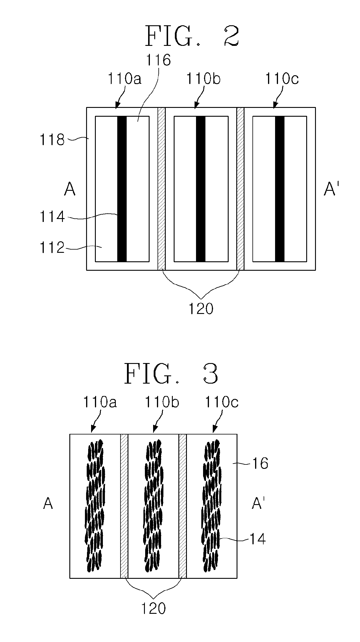
[0063]FIG. 3 is a diagram illustrating a structure of a cross-section of the superconducting coil according to another exemplary embodiment of the present invention.

[0064]Referring to FIG. 3, each of the superconducting wires 110a, 110b, and 110c has a structure of a first-generation wire in which a superconducting portion 14 in the form of a filament is arranged inside a metal matrix, such as a metal stabilizing portion 16. The superconducting portion may be manufactured by a superconducting material, such as Bi2223. Similar to FIG. 2, MIT material layers 120 are interposed between the superconducting wires 110a, 110b, and 110c.

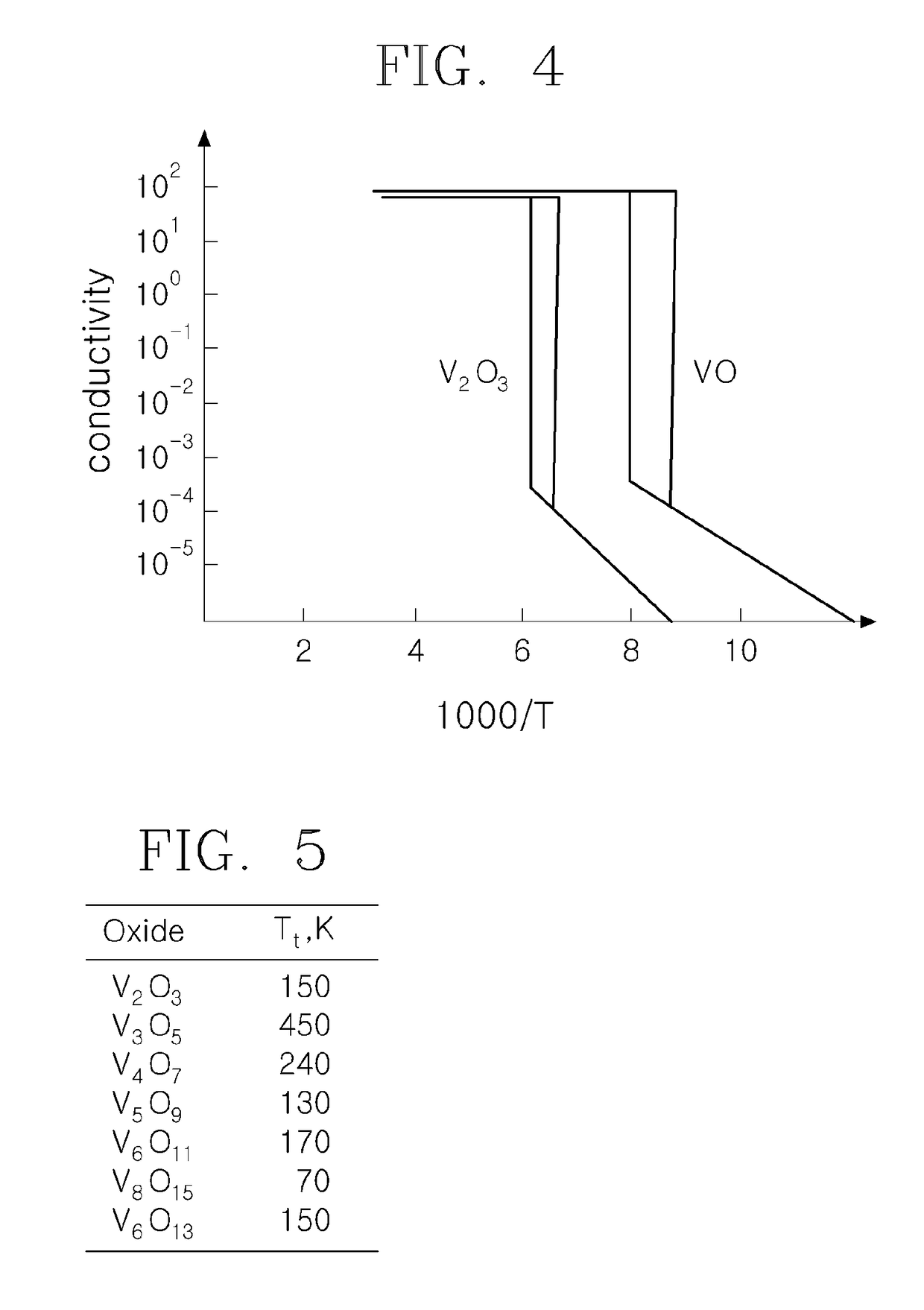
[0065]The MIT described with reference to FIGS. 2 and 3 generally refers to a material which has low electrical conductivity at a temperature less than a predetermined temperature (transition temperature) to operate as an insulator, but exhibits sharp increase in electrical conductivity at the transition temperature or higher.

[0066]Even in the specification...


PUM

PropertyMeasurementUnit
critical temperatureaaaaaaaaaa
transition temperatureaaaaaaaaaa

Abstract

The present invention relates to a superconducting coil having a structure in which an insulation layer electrically insulates the space between adjacent wound wires. The present invention provides a superconducting coil in which superconducting wires extended at a predetermined width in a lengthwise direction are stacked and wound, the superconducting coil comprising a metal-insulator transition (MIT) material layer interposed so as to electrically insulate space between adjacent superconducting wires in the stacking direction of the superconducting wires. According to the present invention, provided is a superconducting coil having high stability, and easily controlling electromagnetic properties including response properties and having a self-protective function against a quench phenomenon and the like during the driving of a magnet.

Description

TECHNICAL FIELD[0001]The present invention relates to a superconducting coil formed by winding of a superconducting wire, and more particularly, to a high-temperature superconducting coil having a structure in which an insulating layer electrically insulates a space between adjacent wound wires.BACKGROUND ART[0002]A high-temperature superconducting wire operating at a liquefied nitrogen temperature exhibits a high threshold current density characteristic at a high magnetic field and attracts attention as application of a high magnetic field of a superconducting magnet and the like.[0003]The high-temperature superconducting wire may have a structure in which a filament or a thin-film type superconducting part is extended within external skin of a conductive metal, and may be divided into a first-generation superconducting wire and a second-generation superconducting wire according to a structure thereof. For example, the second-generation superconducting wire has a structure in which...

Claims


Application Information

Patent Timeline
Patent Type & Authority Applications(United States)
IPC IPC(8): H01F6/06H01B12/04H01B12/14
CPCH01F6/06H01B12/04H01B12/14H01F41/048H01F6/02H01F6/00Y02E40/60
Inventor KIM, SEOG WHANJO, YOUNG SIKKO, ROCK KILHA, DONG WOOKIM, HYUNG WOOKPARK, CHAN
Owner KOREA ELECTROTECH RES INST
Why Eureka
Try Eureka