
Optical sensor housing

a technology for optical sensors and housings, applied in the field of optical sensor housings, can solve problems such as difficult reliability in environments with gps-denied environments, reduced performance in poorly lit or dirty environments, and the lik

Active Publication Date: 2019-03-07
MTD PRODUCTS
View PDF7 Cites 15 Cited by
  • Summary
  • Abstract
  • Description
  • Claims
  • Application Information

AI Technical Summary

Benefits of technology

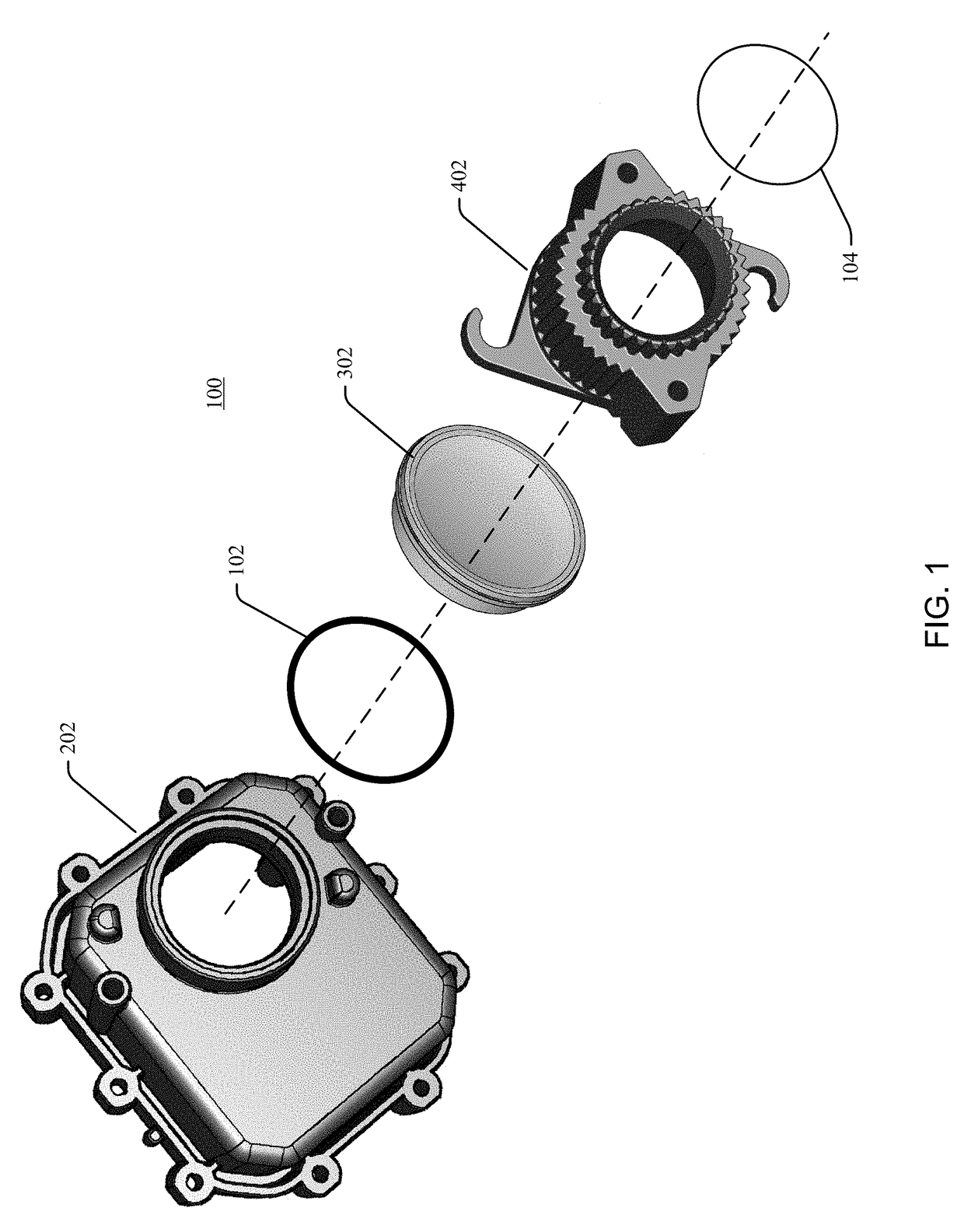
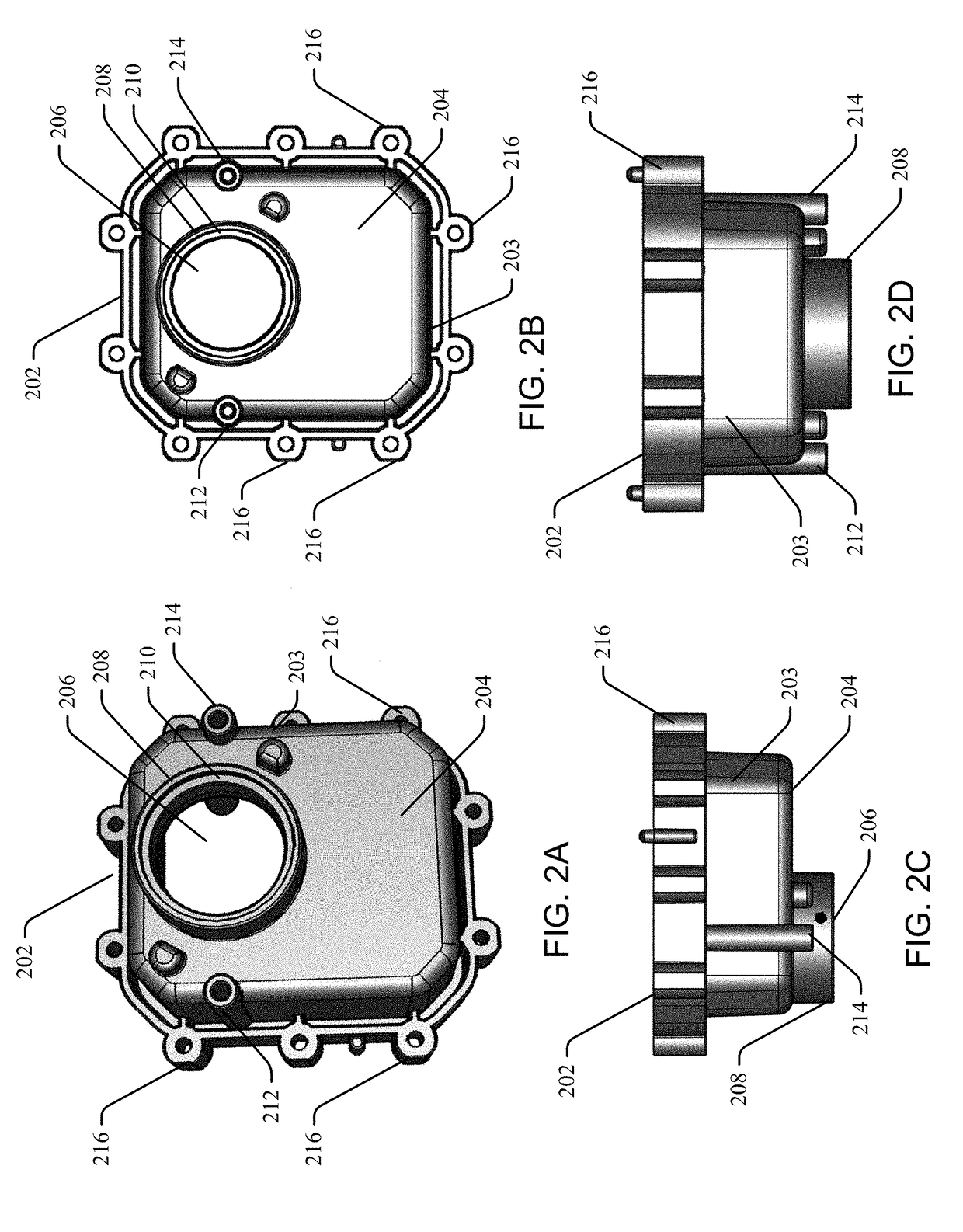
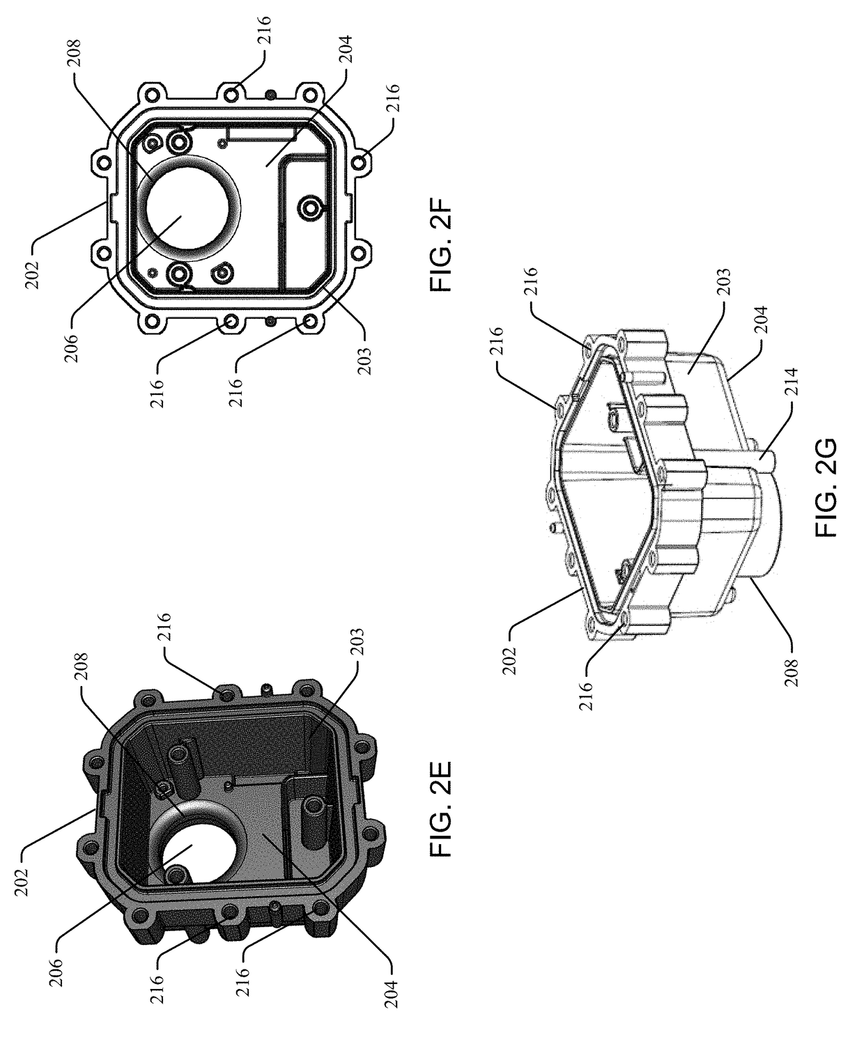
The patent describes a sensor housing for an optical sensor assembly. The sensor housing has a cavity in which the optical sensor assembly is located, with one or more support walls and an open top portion. The sensor housing also has an engaging part that projects orthogonally from the outside surface of the sensor housing body. A sensor housing cover is provided with an open central portion and a flange that engages with the engaging part of the sensor housing body to secure the sensor housing cover to the sensor housing body. The sensor housing cover also has ridges along its length. The technical effects of this design include a quick-lock mechanism for securing the sensor housing cover to the sensor housing body without the use of a fastener or tool, and a seal for the sensor housing body aperture in alignment with the optical window.

Problems solved by technology

Positioning is a key task in most field robotics applications and can be very challenging in GPS-denied environments.
Many applications present significant challenges for positioning strategies utilizing optical sensors, and the use of optical sensors in outdoor environments presents difficulties in terms of reliability.
For example, reduced performance is experienced in poorly lit or dirty environments.
For autonomous device navigation, due to performance and cost considerations, the sensor is located somewhat close to the ground, and is particularly susceptible to blockage or fouling by dirt, debris, grass clippings, and moisture.

Method used


Image

  • Optical sensor housing
  • Optical sensor housing
  • Optical sensor housing

Examples


Embodiment Construction

[0026]Embodiments of an optical sensor housing are disclosed. In the following description numerous specific details are set forth to provide a thorough understanding of the embodiments. One skilled in the relevant art will recognize, however, that the techniques described herein can be practiced without one or more of the specific details, or with other methods, components, materials, etc. In other instances, well-known structures, materials, or operations are not shown or described in detail to avoid obscuring certain aspects.

[0027]Reference throughout this specification to “one embodiment” or “an embodiment” means that a particular feature, structure, or characteristic described in connection with the embodiment is included in at least one embodiment of the disclosure. Thus, the appearances of the phrases “in one embodiment” or “in an embodiment” in various places throughout this specification are not necessarily all referring to the same embodiment. Furthermore, the particular f...


PUM


Abstract

An optical sensor housing includes a sensor housing body including an enclosure wall upstanding from a bottom portion and a substantially open top portion defining a cavity in which the optical sensor assembly is located, at least one aperture, and at least one engaging part projecting orthogonally from an outside surface of the sensor housing body, a sensor housing cover including an open central portion, at least one integrally molded compliant flange configured to engage the sensor housing body engaging part and to secure the sensor housing cover to the sensor housing body, and longitudinal ridges extending outwardly and disposed substantially along the length of the sensor housing cover. The sensor housing engaging parts and flanges can provide a quick-lock mechanism operable to secure the sensor housing cover to the sensor housing body without the use of tools or fasteners.

Description

CROSS REFERENCE TO RELATED APPLICATIONS[0001]This application claims the benefit of U.S. Provisional Application No. 62 / 553,446 filed Sep. 1, 2017, the entire disclosure of which is hereby incorporated herein by reference.FIELD OF THE INVENTION[0002]This disclosure relates generally to housings for optical sensor systems, and in particular but not exclusively, to optical sensor housings for optical sensor systems in an outdoor environment.BACKGROUND OF THE INVENTION[0003]Optical imaging sensors collect coordinate data from object surfaces and can be useful in a wide variety of automation applications, including shape acquisition, assembly, inspection, and autonomous device navigation. The collected image data points represent surface geometry in a sampled form. The optical odometer is an active optical sensor that measures relative motion of a moving platform.[0004]Positioning is a key task in most field robotics applications and can be very challenging in GPS-denied environments. A...

Claims


Application Information

Patent Timeline
IPC IPC(8): H04N5/225H05K5/02H05K5/00
CPCH04N5/2253H04N5/2252H05K5/0247H05K5/0004H05K5/0073G02B7/02G02B7/022H04N23/54H04N23/51
Inventor MAGGARD, JAY E.GORSAGE, GREGORYSMITH, AARON D.
Owner MTD PRODUCTS
Learn More