Helmet insert

a technology for inserts and helmets, applied in helmets, sports equipment, helmets, etc., can solve the problems of limited deformation distance, increased head injury risk, increased propensity for overheating, etc., and achieves the effect of widening the performance window of inserts and effective protection

Inactive Publication Date: 2019-03-14
PEMBROKE BOW LTD
View PDF0 Cites 14 Cited by
  • Summary
  • Abstract
  • Description
  • Claims
  • Application Information

AI Technical Summary

Benefits of technology

[0006]The Miura-Ori fold geometry provides a strong and lightweight structure with good energy absorption characteristics. The Miura-Ori fold geometry also provides several parameters that can be varied, allowing its properties to be tuned to a particular application. For example, different helmet inserts could be provided for wearers who play different positions in an American football team. It will be appreciated that the layers need not be identical, and it may be advantageous to provide certain layers with different geometries. Further layers may be provided which do not have a Miura-Ori fold geometry.
[0033]This allows different structures to be trialled in the manufacturing process, varying according to parameters such as fold angles, wall thickness, the relative orientations of the layers and the orientation of the stacking direction of the layers within the helmet. The configuration that minimises the acceleration of the head of the wearer in a given impact situation may thus be determined. The combination of finite element analysis and additive manufacturing allows the parameter space to be explored more rapidly and cost-effectively than was possible with previous design and manufacturing techniques.

Problems solved by technology

The available deformation distance is limited by the thickness of the insert, which is ideally small as thicker inserts make the helmet unwieldly, and may in some cases increase the risk of head injury.
Thicker inserts may also increase the propensity for overheating, or require additional air vents to be provided.
It is also desirable to minimise the weight of the insert, as heavier helmets also increase the risk of head injury and may fatigue the wearer after extended use.

Method used


Image

  • Helmet insert
  • Helmet insert
  • Helmet insert

Examples


Embodiment Construction

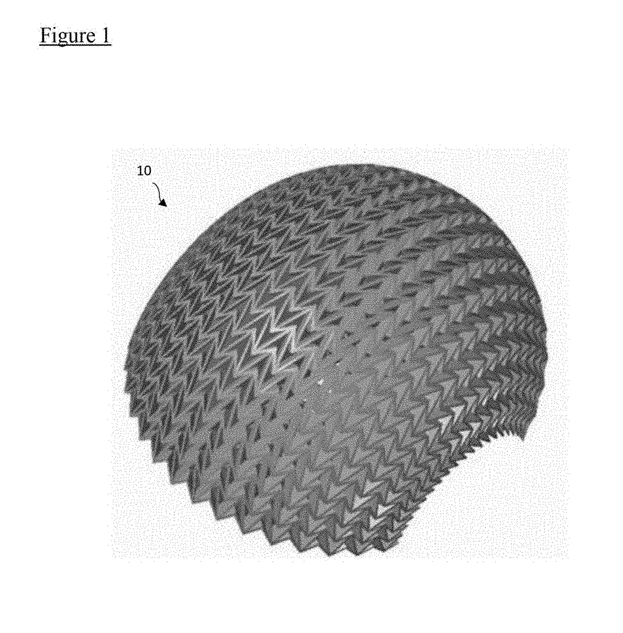
[0045]Referring firstly to FIG. 1, an insert for a helmet is indicated generally at 10. The insert 10 is intended to be fitted within a substantially hard outer shell of a helmet. A soft liner is intended to be inserted into the interior of the insert 10 to sit between the insert 10 and the wearer's head in use. The insert 10 comprises a plurality of layers (not labelled in FIG. 1 in the interests of clarity). The insert 10 has a curved outer surface adapted to abut an inner surface of a helmet outer layer in use.

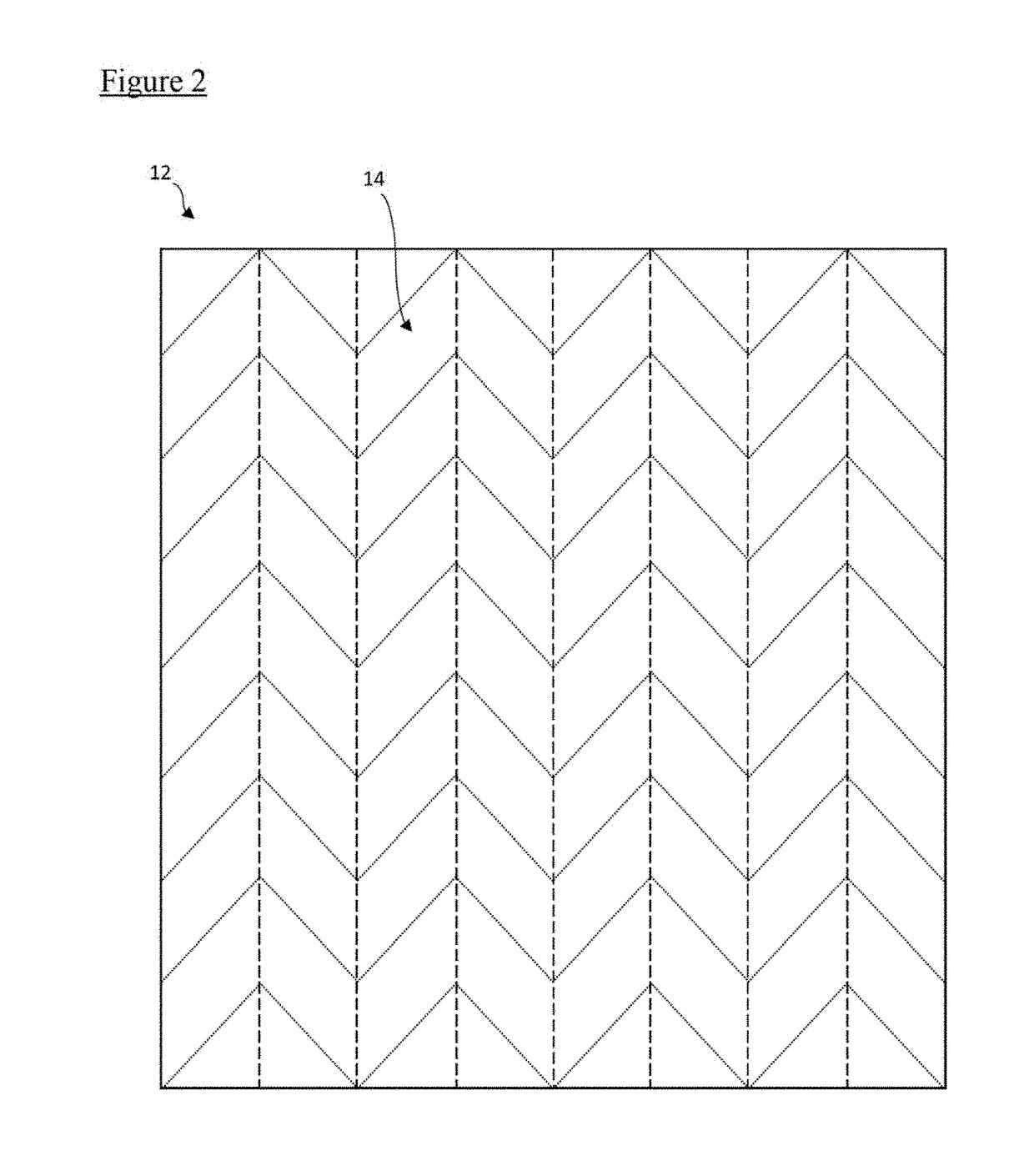
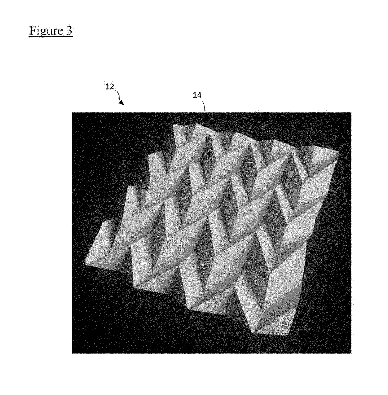
[0046]The layers are described below with reference to a single exemplary layer 12. The exemplary layer consists of a sheet of material folded to produce a three-dimensional structure. The exemplary layer 12 has a planar overall geometry, that is, it is substantially flat. However, it will be understood that the layers used in the helmet have a curved overall geometry. The features of the layers of the helmet insert 10 are small relative to the radius of curvature of the he...


PUM


Abstract

An insert for a helmet comprises a plurality of layers, each layer being of a Miura-Ori fold geometry.

Description

[0001]The present invention relates to a shock absorbing insert for a helmet.BACKGROUND TO THE INVENTION[0002]Helmets are used to protect a wearer's head from potential impacts to prevent head injury, particularly damage to the brain. Helmets are worn for this purpose in a variety of situations: in sports, such as horse riding or climbing, military operations, work in construction or industry or riding motorcycles. A typical helmet for use in such applications may comprise a hard outer shell made of a lightweight high-strength material, typically a plastics material, possibly including Kevlar, and at least one shock absorbing insert inside the outer shell.[0003]In the event of an impact, the outer shell serves to spread the impact force over a larger area, protecting against penetrating impacts. The shock absorbing insert deforms and absorbs kinetic energy, reducing the acceleration of the wearer's head to minimise the chance of damaging the wearer's brain. It is desirable to maximi...

Claims


Application Information

Patent Timeline
Patent Type & Authority Applications(United States)
IPC IPC(8): A42B3/12
CPCA42B3/124A63B71/10
Inventor BUREK, ROY
Owner PEMBROKE BOW LTD
Why Eureka
Try Eureka