Renewable energy powering system

a technology of renewable energy and powering system, which is applied in the direction of propulsion parts, electric propulsion mounting, transportation and packaging, etc., can solve the problems of not perfect traditional techniques

Inactive Publication Date: 2019-03-14
STANLEY II ROBERT E
View PDF33 Cites 24 Cited by
  • Summary
  • Abstract
  • Description
  • Claims
  • Application Information

AI Technical Summary

Benefits of technology

[0038]From reading the present disclosure, other variations and modifications will be apparent to persons skilled in the art. Such variations and modifications may involve equivalent and other features which are already known in the art, and which may be used instead of or in addition to features already described herein.

Problems solved by technology

In view of the foregoing, it is clear that these traditional techniques are not perfect and leave room for more optimal approaches.

Method used


Image

  • Renewable energy powering system
  • Renewable energy powering system
  • Renewable energy powering system

Examples


Embodiment Construction

[0020]The present invention is best understood by reference to the detailed figures and description set forth herein.

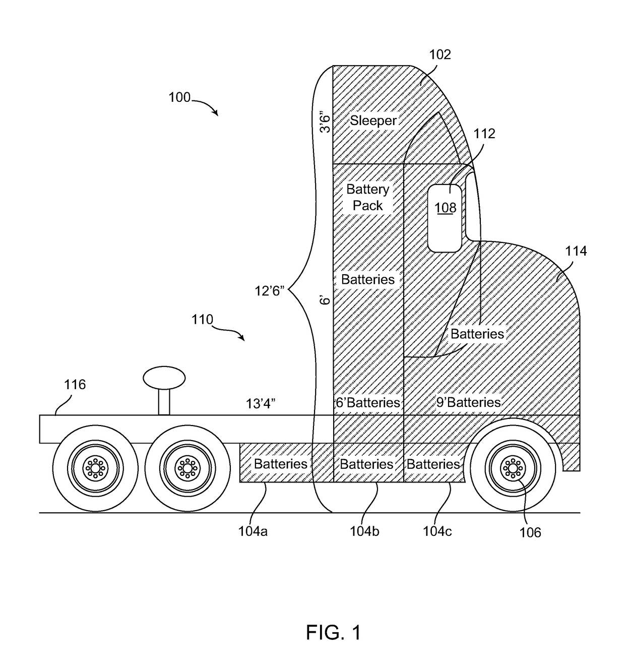
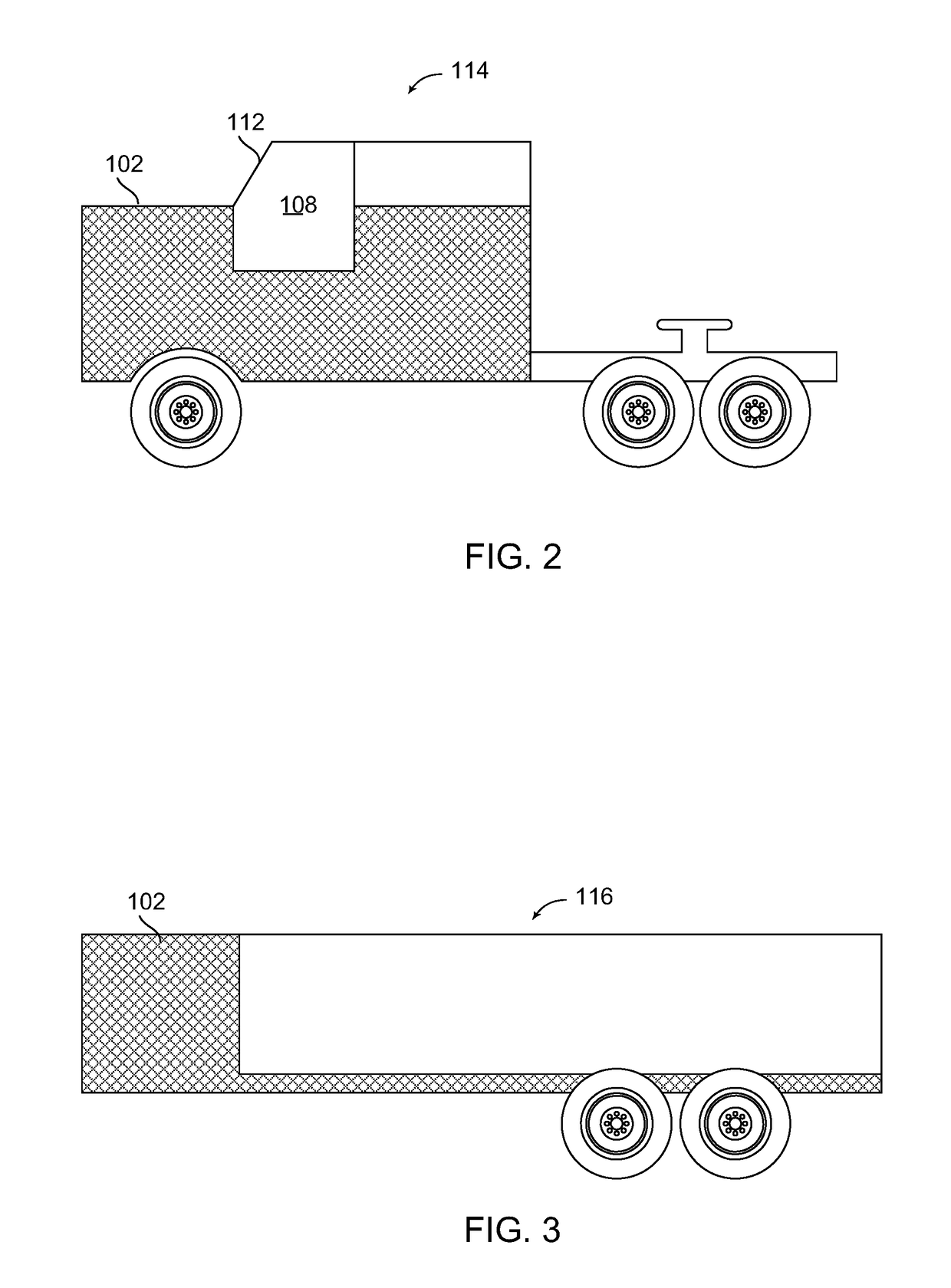
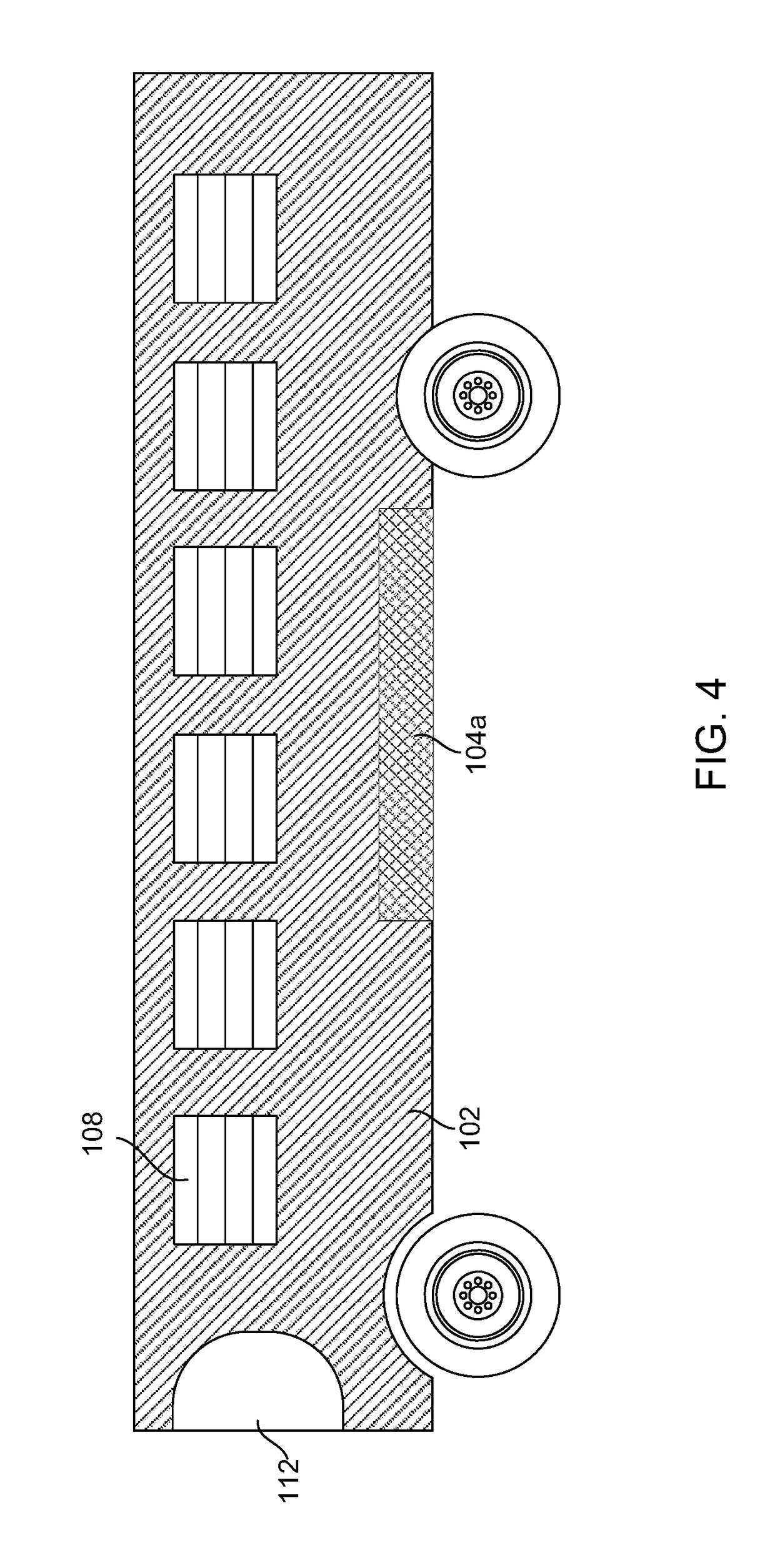
[0021]Embodiments of the invention are discussed below with reference to the Figures. However, those skilled in the art will readily appreciate that the detailed description given herein with respect to these figures is for explanatory purposes as the invention extends beyond these limited embodiments. For example, it should be appreciated that those skilled in the art will, in light of the teachings of the present invention, recognize a multiplicity of alternate and suitable approaches, depending upon the needs of the particular application, to implement the functionality of any given detail described herein, beyond the particular implementation choices in the following embodiments described and shown. That is, there are modifications and variations of the invention that are too numerous to be listed but that all fit within the scope of the invention. Also, singular ...


PUM


Abstract

An alternative energy system utilizes a combination of renewable energy components creating a synergy for generating electricity to power a large vehicle. The renewable energy components include, a primary solar panel, a transparent solar panel, and a brake apparatus. The primary solar panel and the transparent solar panel substantially cover the surface area of a vehicle. The primary solar panel and the transparent solar panel have an ultrathin configuration to enable enhanced resiliency, and to at least partially wrap around a substantial portion of the surface area of the vehicle, including the windows. The brake apparatus includes a regenerative brake that converts kinetic energy of the moving vehicle to electricity when the brakes are applied. The generated electricity is carried to an electricity storage device that selectively powers an electric motor. The system is effective with large vehicles that have spacious surface area and large kinetic energy when braking.

Description

CROSS-REFERENCE TO RELATED APPLICATIONS[0001]Not applicable.RELATED CO-PENDING U.S. PATENT APPLICATIONS[0002]Not applicable.INCORPORATION BY REFERENCE OF SEQUENCE LISTING PROVIDED AS ATEXT FILE[0003]Not applicable.FEDERALLY SPONSORED RESEARCH OR DEVELOPMENT[0004]Not applicable.REFERENCE TO SEQUENCE LISTING, A TABLE, OR A COMPUTER LISTING APPENDIX[0005]Not applicable.COPYRIGHT NOTICE[0006]A portion of the disclosure of this patent document contains material that is subject to copyright protection by the author thereof. The copyright owner has no objection to the facsimile reproduction by anyone of the patent document or patent disclosure for the purposes of referencing as patent prior art, as it appears in the Patent and Trademark Office, patent file or records, but otherwise reserves all copyright rights whatsoever.BACKGROUND OF THE RELEVANT PRIOR ART[0007]One or more embodiments of the invention generally relate to a renewable energy powering system. More particularly, certain embo...

Claims


Application Information

Patent Timeline
Patent Type & Authority Applications(United States)
IPC IPC(8): B60K16/00B60K6/10B60K6/28
CPCB60K16/00B60K6/10B60K6/28B60K2016/003B60K1/04B60K2001/0416B60K2001/0438B60Y2200/14B60Y2200/142B60Y2200/148B60Y2200/30Y02T10/90
Inventor STANLEY, II, ROBERT E.
Owner STANLEY II ROBERT E
Why Eureka
Try Eureka