
Unmanned aerial vehicle

a technology of unmanned aerial vehicles and projectiles, which is applied in the direction of launching/towing gear, process and machine control, instruments, etc., can solve the problems of inability of operatives to survey or defeat enemy targets in defilade positions or behind cover, and the trajectory of projectiles cannot be altered once fired

Active Publication Date: 2019-03-14
DEFENDTEX
View PDF42 Cites 20 Cited by
  • Summary
  • Abstract
  • Description
  • Claims
  • Application Information

AI Technical Summary

Benefits of technology

The patent describes a system where a drone is attached to a missile or grenade and can be used to steer it towards a target. This allows for more accurate and efficient targeting, particularly in situations where there are multiple drones or limited visibility. The drone can also be designed to protect the internal components of the missile or grenade during storage and handling. The system is controlled by a human operator who can change direction and engage with targets as needed. This technology provides a further advantage for operatives who need to adapt to changing situations and target movements.

Problems solved by technology

Present day munitions, in particular small arms grenade munitions, have a significant drawback where in order to accurately reach the target, operatives generally require a direct line of sight.
This makes it difficult for operatives to survey or defeat enemy targets in defilade positions or behind cover, such as an intervening crest of a hill, or behind trees.
Another disadvantage of these munitions is they are generally only capable of following a substantially parabolic trajectory, with the trajectory of the projectile unable to be altered once fired.

Method used


Image

  • Unmanned aerial vehicle
  • Unmanned aerial vehicle
  • Unmanned aerial vehicle

Examples


Embodiment Construction

[0036]The invention is suitable for deployment from a projectile casing and launched by a grenade launcher, and it will be convenient to describe the invention in relation to that exemplary, but non-limiting, application.

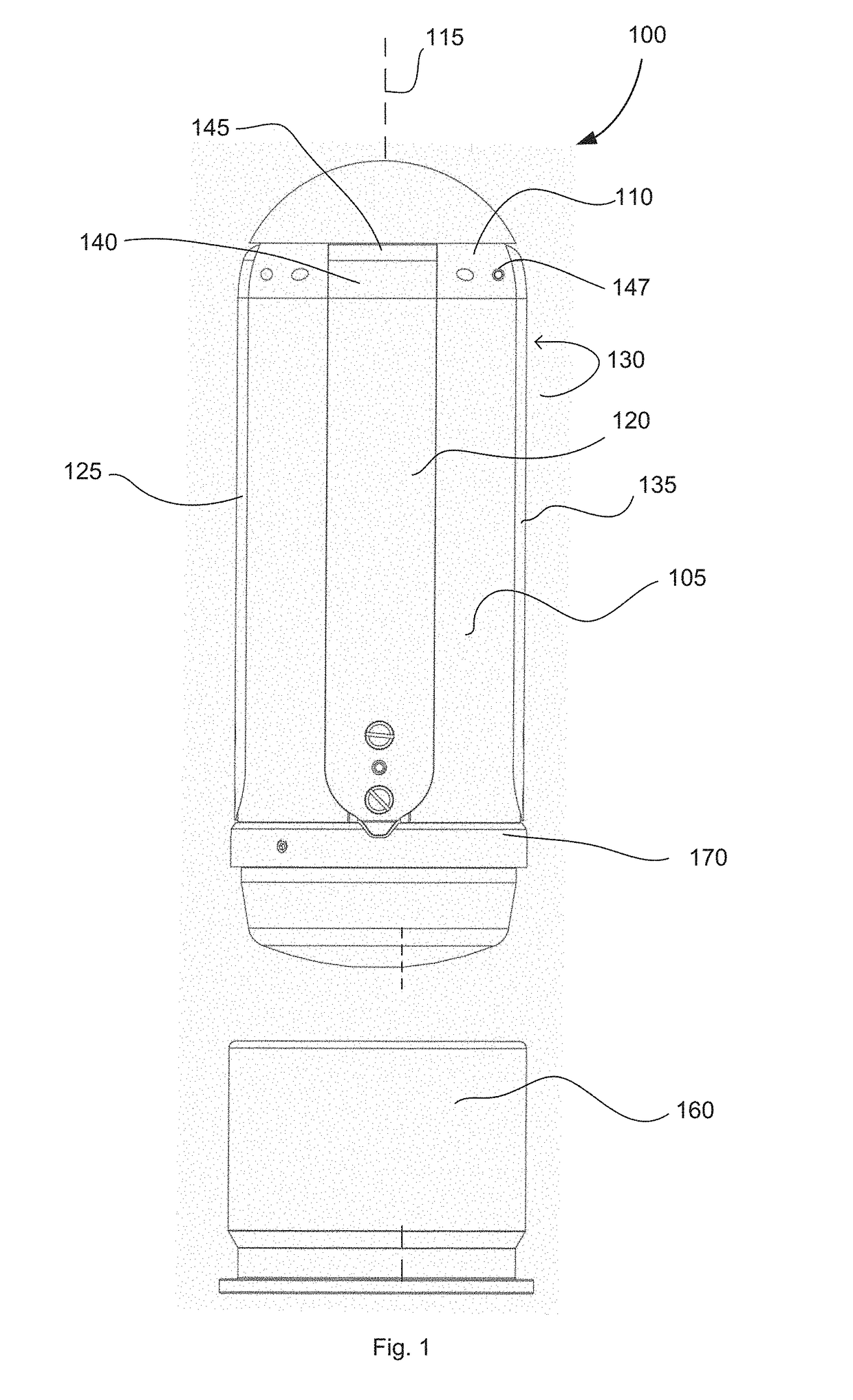
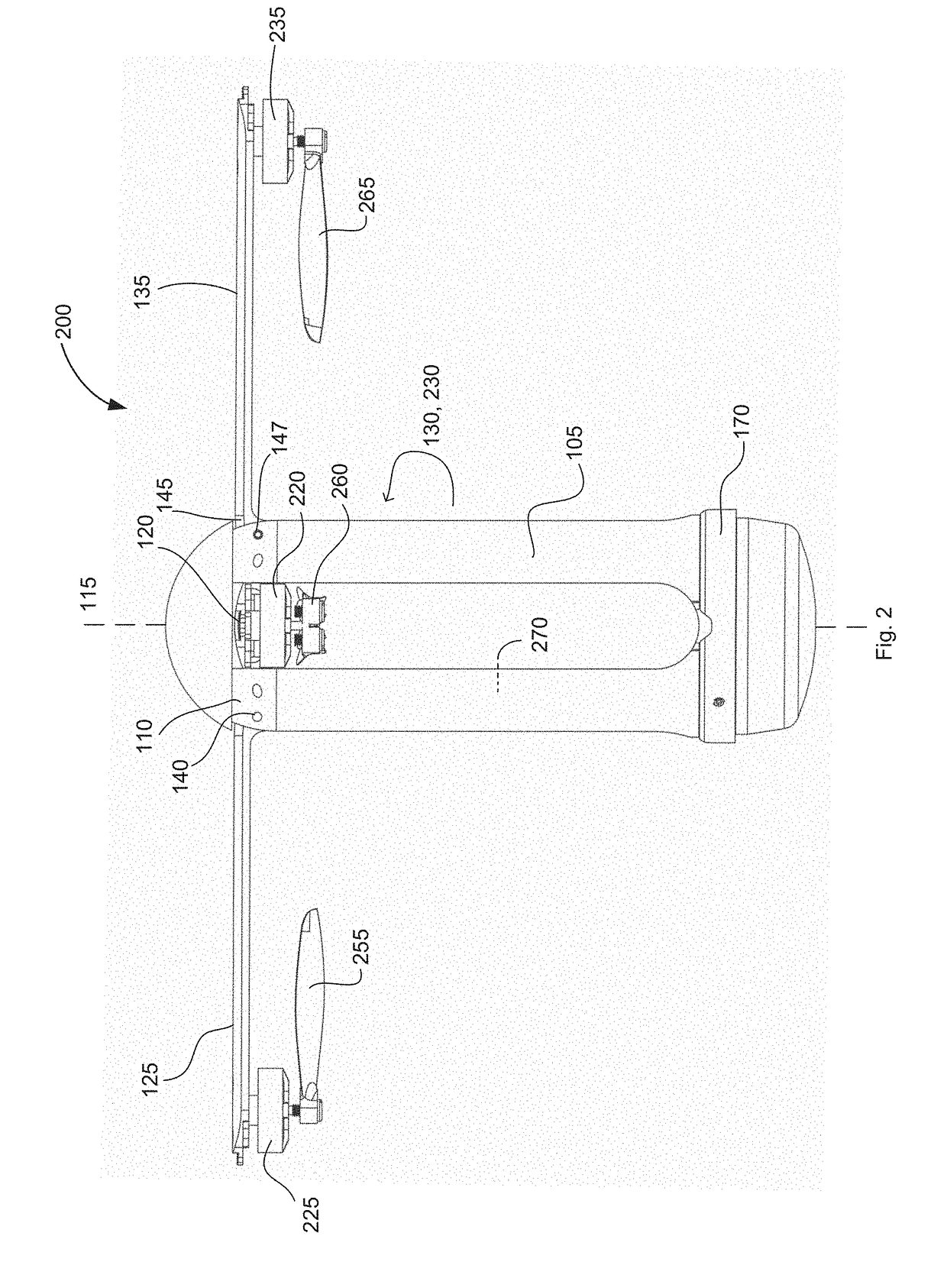
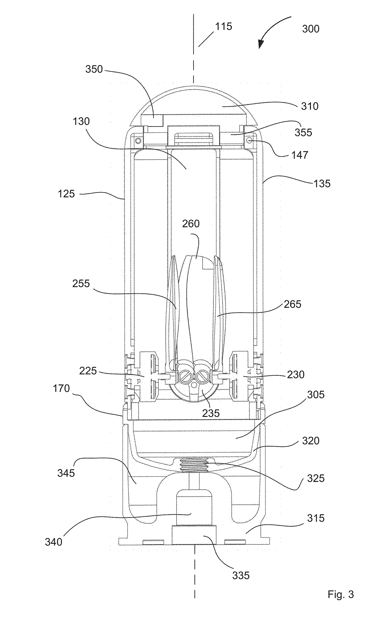
[0037]Referring firstly to FIG. 1, there is shown a side view of an exemplary embodiment of a UAV 100 in a closed position. The UAV 100 includes a projectile casing 105 and a wing assembly 110, mechanically connected as shown, with a removable cartridge 160, shown as removed from UAV 100. In the closed position, wing assembly 110 is substantially integral with projectile casing 105 to effect aerodynamic flight along axis 115 when the UAV 100 is thrown or projected into a trajectory.

[0038]According to the embodiment shown, wing assembly 110 may comprise four rotor arms: a first rotor arm 120; a second rotor arm 125; a third rotor arm 130; and, a fourth rotor arm 135. Wing assembly 110 is mechanically connected to projectile casing 105 via a hinge 140 and a mounting f...


PUM


Abstract

An unmanned aerial vehicle (UAV) adapted for transit in and deployment from a projectile casing is provided. The UAV includes a wing assembly coupled to the projectile casing and the wing assembly moveable between a closed position and a deployed position. The UAV further includes a propulsion system including at least one rotor disposed on the wing assembly to generate lift, wherein in the closed position, the wing assembly is substantially integral with the projectile casing and in the deployed position, the wing assembly is extended outwards from the projectile casing.

Description

[0001]The present invention generally relates to an unmanned aerial vehicle (UAV).BACKGROUND OF INVENTION[0002]Modern warfare often involves operatives working in close confines with civilians, civilian targets and friendly personnel. As stray engagements often have very serious consequences, including civilian casualties and / or collateral damage, it is desirable only to engage with enemy targets and personnel.[0003]In modern warfare, it is well recognised that an effort is usually made to concentrate the greatest number of munitions on to a desired target, and any improvements in the probability of the munitions engaging with that target are readily sought. Present day munitions, in particular small arms grenade munitions, have a significant drawback where in order to accurately reach the target, operatives generally require a direct line of sight. Further, operatives must estimate the parabolic trajectory, allowing for differences in distance, altitude, atmospheric conditions, the...

Claims


Application Information

Patent Timeline
Patent Type & Authority Applications(United States)
IPC IPC(8): B64C39/02B64C1/06B64C13/16B64C27/39B64C27/08G05D1/00F42B10/58F42B30/10
CPCB64C39/024B64C1/063B64C13/16B64C27/39B64C27/08G05D1/0027F42B10/58F42B30/10B64C2201/084B64C2201/201B64C2201/024B64C2201/141B64C2201/146B64C2201/121F42B15/08F42B30/04F41G3/145F41G9/002B64U10/14B64U20/50B64U2101/15B64U70/50B64U30/29F42B10/14B64F1/10B64U70/70B64U80/70B64U2201/10B64U2201/20B64U2201/104
Inventor REDDY, TRAVISCAHILL, DAMIEN
Owner DEFENDTEX
Learn More