Displacement control valve

a technology of displacement control valve and displacement control valve, which is applied in the direction of positive displacement liquid engine, pump parameter, machine/engine, etc., can solve the problems of reducing the operating efficiency of variable displacement compressor, unable to achieve the discharge rate as set, and unable to avoid the reduction of the operating efficiency of the variable displacement compressor during control

Active Publication Date: 2019-03-14
EAGLE INDS
View PDF4 Cites 4 Cited by
  • Summary
  • Abstract
  • Description
  • Claims
  • Application Information

AI Technical Summary

Benefits of technology

[0027]The present invention achieves the following outstanding effects.

Problems solved by technology

Thus, unless the liquid refrigerant is discharged, a discharge rate as set cannot be achieved by the compression of the refrigerant gas.
In the above conventional art, however, the refrigerant gas flows from the control chamber into the suction chamber even when the space between the first valve section 79 and the valve seat surface of the valve seat element 80 is in a closed state and the flow of the fluid through the auxiliary communicating passage 85 is unnecessary, for example, during the control of the variable displacement compressor, thus resulting in a reduction in the operating efficiency of the variable displacement compressor.
Thus, the variable displacement compressor cannot avoid a reduction in operating efficiency during control.

Method used


Image

  • Displacement control valve
  • Displacement control valve
  • Displacement control valve

Examples


first embodiment

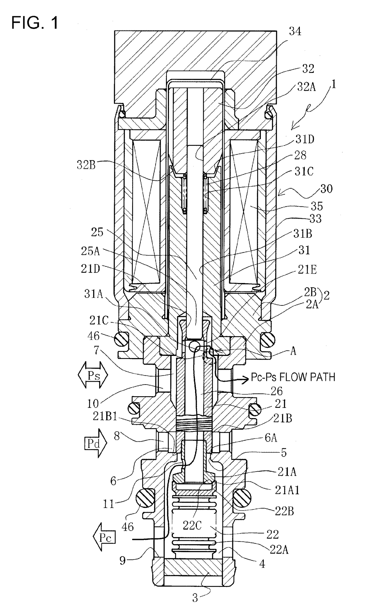
[0037]With reference to FIGS. 1 to 3, a displacement control valve according to a first embodiment of the present invention will be described.

[0038]In FIG. 1, reference numeral 1 denotes a displacement control valve. The displacement control valve 1 is provided with a valve body 2 forming an outside shape. The valve body 2 includes a first valve body 2A having a through hole provided with functions inside, and a second valve body 2B integrally fitted to one end of the first valve body 2A. The first valve body 2A is made of a metal such as brass, iron, aluminum, or stainless, or a synthetic resin material, or the like. The second valve body 2B is formed of a magnetic substance such as iron.

[0039]The second valve body 2B is provided separately to be different in function from the material of the first valve body 2A because a solenoid unit 30 is connected to the second valve body 2B, and the second valve body 2B must be of a magnetic substance. If this point is considered, the shape sh...

second embodiment

[0072]With reference to FIGS. 4 to 6, a displacement control valve according to a second embodiment of the present invention will be described.

[0073]The displacement control valve according to the second embodiment includes a third valve section 41C and a third valve seat surface 51A that are different in shape from the third valve section 21C and the third valve seat surface 31A of the displacement control valve according to the first embodiment, but is identical to that of the first embodiment in the other basic configuration. The same reference numerals and letters are assigned to the same members without duplicated explanation.

[0074]In FIGS. 5A to 5C, the third valve seat surface 51A has a cylindrical shape including an inner-diameter surface portion 51Aa, an outer-diameter surface portion 51Ab, and a valve seat 51Ac extending in a direction that is at right angles to the travel direction of the valve element 21.

[0075]The third valve section 41C opposite the third valve seat sur...


PUM


Abstract

A displacement control valve improved in the function of discharging a liquid refrigerant in a control chamber at startup achieves a reduction in startup time and an improvement in operating efficiency during control of a variable displacement compressor simultaneously. An opening area between a third valve section and a third valve seat surface in a control area to control the flow rate or pressure in a working control chamber is set smaller than an area of an auxiliary communicating passage, thereby reducing the minimum area of a Pc-Ps flow path in the control area.

Description

CROSS-REFERENCE TO RELATED APPLICATIONS[0001]This application is a U.S. National Stage Application of International Application No. PCT / JP2017 / 009642, filed on Mar. 10, 2017, and published in Japanese as WO 2017 / 159553 on Sep. 21, 2017 and claims priority to Japanese Application No. 2016-054050, filed on Mar. 17, 2016. The entire disclosures of the above applications are incorporated herein by reference.BACKGROUNDTechnical Field[0002]The present invention relates to a displacement control valve that variably controls the displacement or pressure of a working fluid, and more particularly, relates to a displacement control valve that controls the discharge rate of a variable displacement compressor or the like used in an air-conditioning system of an automobile or the like, according to pressure load.Related Art[0003]A swash-plate variable displacement compressor used in an air-conditioning system of an automobile or the like includes a rotating shaft rotationally driven by the torque...

Claims


Application Information

Patent Timeline
Patent Type & Authority Applications(United States)
IPC IPC(8): F04B27/18F04B49/12F16K11/02F16K11/07
CPCF04B49/12F16K11/025F04B27/18F16K11/0716F04B2027/1827F04B2027/1813F04B2027/1859F04B2201/0206F04B27/1804F04B2027/1831F16K11/02
Inventor HAYAMA, MASAHIROHIGASHIDOZONO, HIDEKIFUKUDOME, KOHEIKURIHARA, DAICHI
Owner EAGLE INDS
Why Eureka
Try Eureka