Coupler for releasably securing integrated segments of an assemblage against otherwise accomodated relative translational displacement

a technology of integrated segments and couplings, which is applied in the direction of fastening means, rod connections, stands/trestles, etc., can solve the problems of shortening the useful life, overly complex couplers, and expensive production and replacement, etc., and achieves the effects of less expensive production, simple use and light weigh

Active Publication Date: 2019-03-14
ZUBY LLC
View PDF0 Cites 4 Cited by
  • Summary
  • Abstract
  • Description
  • Claims
  • Application Information

AI Technical Summary

Benefits of technology

[0005]This invention provides a coupling apparatus for releasably securing integrated segments of an assemblage. The coupler apparatus is characterized by design simplicity (including only a carrier and a restraining wedge for releasably securing the integrated segments of the assemblage), is thus less expensive to produce, and requires no secondary mechanisms or hardware in use to achieve segment position retention. The apparatus is simple to use and is light-weight yet strong, durable and reliable even where use requires numerous repeated engagements and releases of the coupler over the product life cycle of the assemblage. The coupler of this invention is particularly well adapted for use with telescoping segments of an assemblage to improved weight bearing capacity of the integrated segments without segment joint slippage.

Problems solved by technology

For example, telescoping couplers are often limited in weight bearing capacity without joint slippage at couplers, and or often heavy due to the use of threaded fasteners or components with ferrules or collets used as a compression coupler.
Threaded fastener used in many couplers present a recurring frustration for users where repeated tightening and loosening is required during use, the strength of the user thus being a factor and the process being time consuming, and where rapid wear of such couplers shortens the useful life thereof.
Heretofore known couplers are also overly complex and expensive to produce (and thus replace) and often require separate actuators or fasteners for coupler use.

Method used


Image

  • Coupler for releasably securing integrated segments of an assemblage against otherwise accomodated relative translational displacement
  • Coupler for releasably securing integrated segments of an assemblage against otherwise accomodated relative translational displacement
  • Coupler for releasably securing integrated segments of an assemblage against otherwise accomodated relative translational displacement

Examples


Embodiment Construction

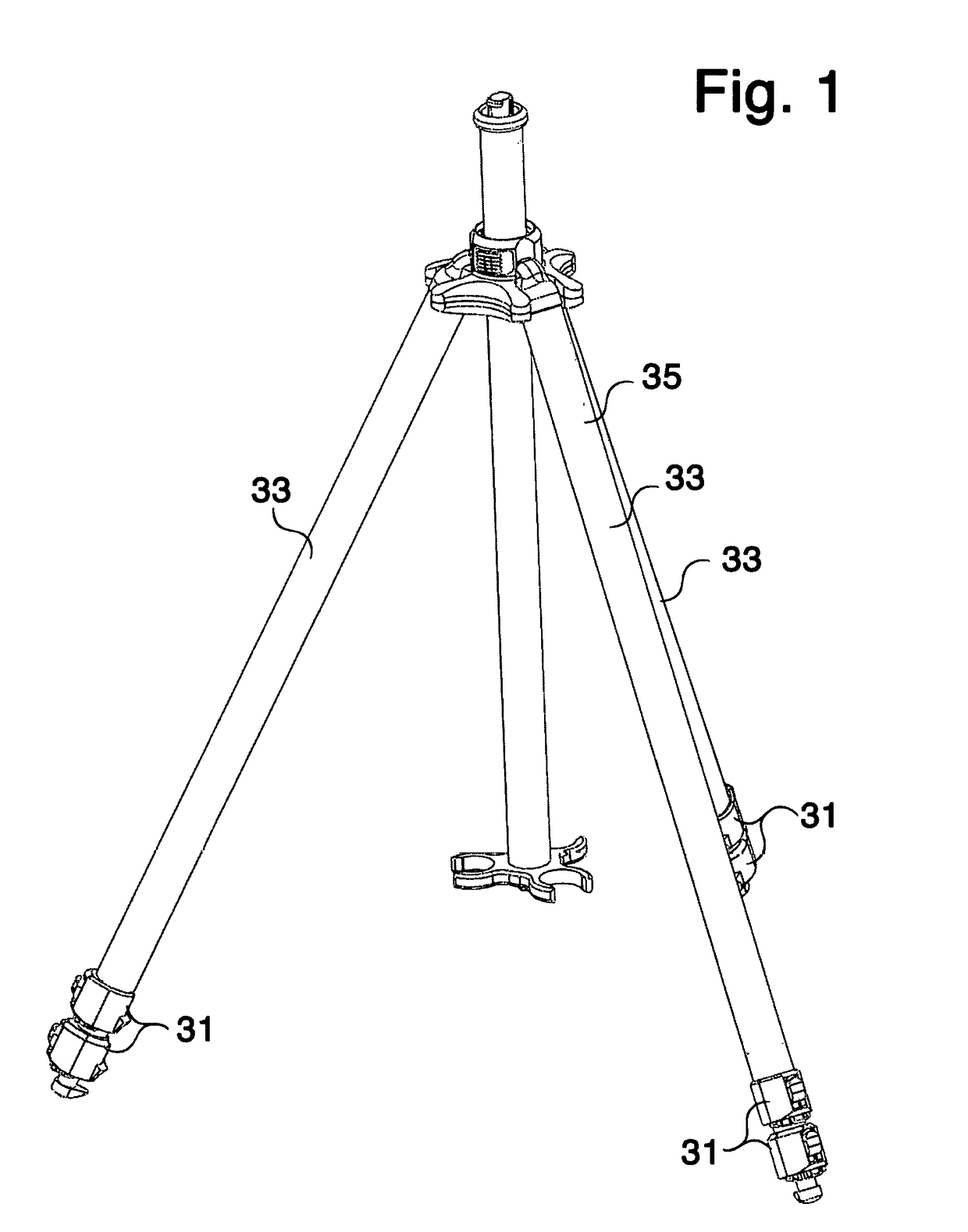
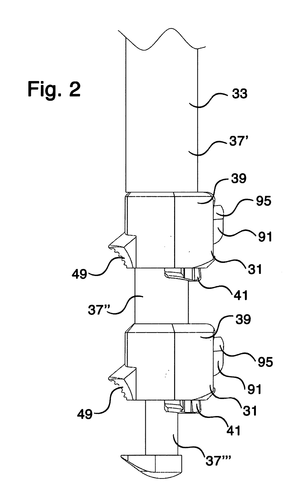
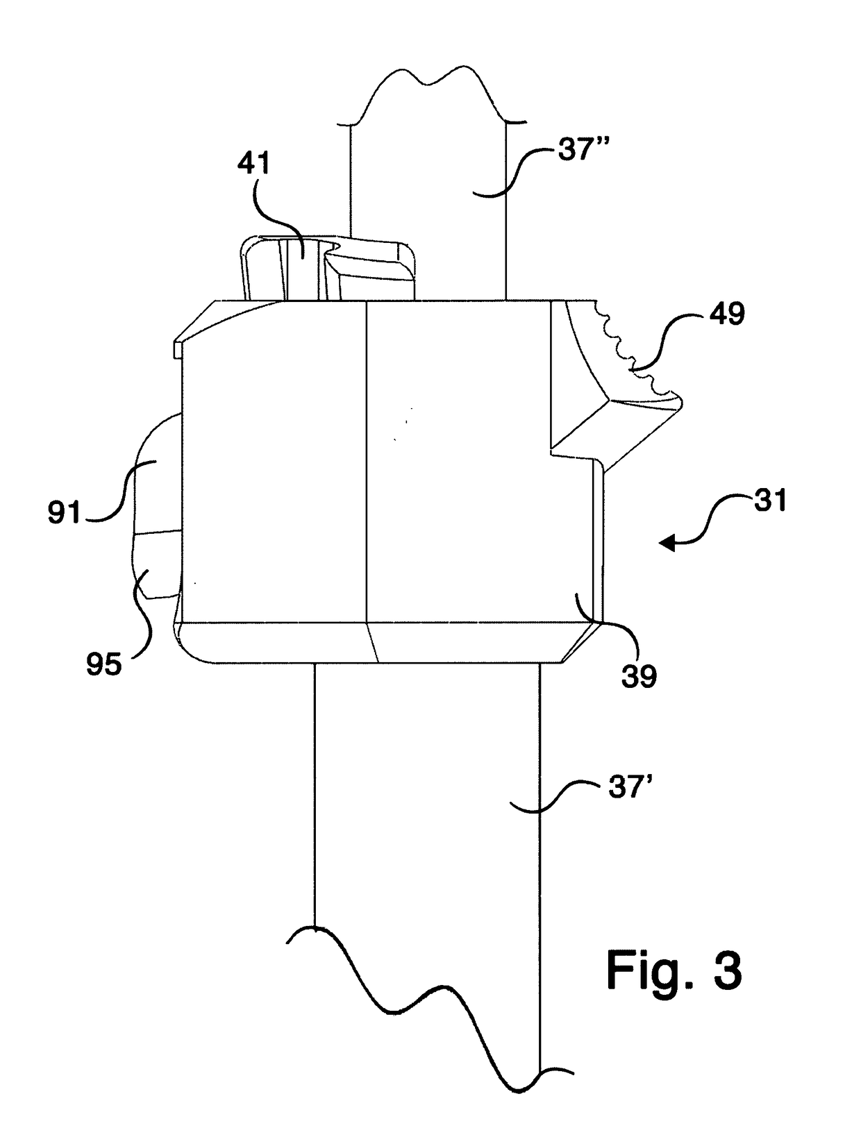
[0041]With reference to FIGS. 1 through 9, a first embodiment of coupling apparatus (or simply coupler) 31 of this invention will be described. As shown in FIG. 1, coupler 31 is deployed with telescoping leg assemblages 33 of a tripod 35 (other deployment schemes will be described hereinbelow). As seen in FIGS. 2 and 3, telescoping legs 33 include plural leg segments 37′, 37″ and 37′″ telescopingly housed one in the next (a plurality of legs of any number are used depending upon the product and its use, coupler 31 variously sized and configured to accommodate any telescoping leg segment pair).

[0042]Coupler 31 includes carrier 39 and restraint (or wedge) 41. Carrier 39 (see FIGS. 4, 5, 8 and 9) has first and second opposite ends 43 and 45, with connecting sleeve 47 at end 43 and a protruding gripping surface 49 and inwardly tapering lip 51 at collar 52 of opposite open end 45. Internal cavity 53 is located in carrier 39 between the ends with spaced wall portions 55 and 57 at opposite...


PUM


Abstract

Apparatus are disclosed for coupling integrated segments of an assemblage. The coupler apparatus includes a carrier connectable to one segment and slidably receiving another segment and has an elongate slot defined at one wall portion of a cavity therein. A restraint includes a conic wedge receivable in the carrier and has an actuator arm angularly extending from the wedge that is receivable through the elongate slot of the carrier.

Description

FIELD OF THE INVENTION[0001]This invention relates to mechanical couplers and, more particularly, relates to couplers for releasably securing integrated units (such as telescoping segments) from relative translatory motion in at least one direction.BACKGROUND OF THE INVENTION[0002]A variety of applications for assemblages having segments capable of relative movement for coupling the segments and / or for accommodating adjustment of a dimension of the assemblage (such as length) are well known and widely utilized. Examples of such assemblages include telescoping tube, rod and / or cylinder segments for setting specific length extensions of the assemblage from a stored association of the segments. Typical applications include adjustable legs for bipods and tripods, easels, light stands, hospital bed stands, tables , bicycle posts and mounting tubes, strain reliefs for cable and fiber optics, and a large variety of other such applications. Another example of such assemblages includes a hos...

Claims


Application Information

Patent Timeline
Patent Type & Authority Applications(United States)
IPC IPC(8): F16M11/32
CPCF16M11/32F16B7/14F16B7/1463F16M11/28F16M2200/027F16B7/16
Inventor WILSON, DAVID S.WILSON, JR., DAVID
Owner ZUBY LLC
Why Eureka
Try Eureka