Shielded conductive path and relay connecting member

a shielding conductive path and relay technology, applied in the direction of insulated conductors, cable connections, coupling devices, etc., can solve the problems of complex shape of shielding members and difficult manufacturing of shielding members

Inactive Publication Date: 2019-03-14
SUMITOMO WIRING SYST LTD
View PDF14 Cites 2 Cited by
  • Summary
  • Abstract
  • Description
  • Claims
  • Application Information

AI Technical Summary

Benefits of technology

[0006]The present disclosure was made based on such circumstances as described above, and it is an object thereof to provide a shielded conductive path that can be adapted to a branch structure without making the shape of a shielding member more complex.

Problems solved by technology

In the above-described case, when the branch structure of the shielded conductive path is complex, the shape of the shielding member also becomes complex.
However, since the shielding member is a braided member formed by braiding thin metal wires in the manner of a mesh, it is difficult to adapt the shielding member to a complex branch structure, and there is a risk that the shielding member will be difficult to manufacture.

Method used


Image

  • Shielded conductive path and relay connecting member
  • Shielded conductive path and relay connecting member
  • Shielded conductive path and relay connecting member

Examples


embodiment 1

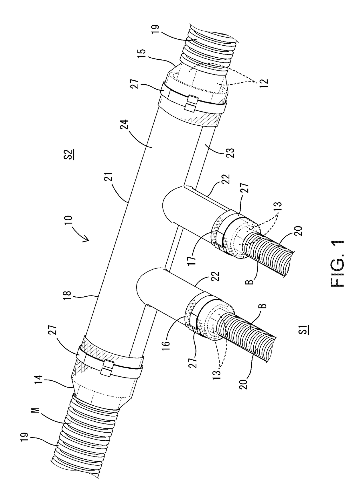
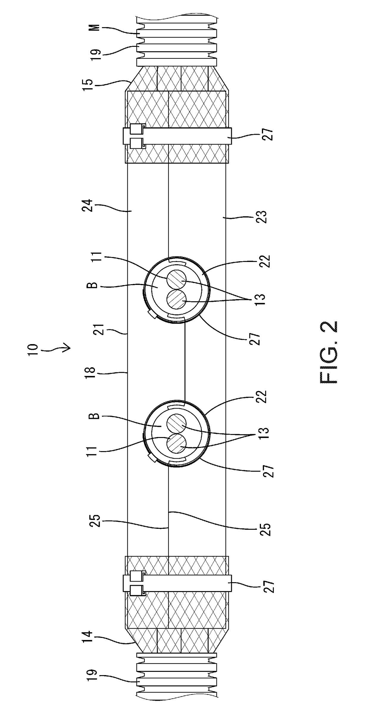
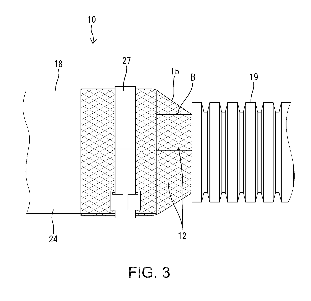
[0028]Hereinafter, Embodiment 1 will be described based on FIGS. 1 to 9. A shielded conductive path 10 according to Embodiment 1 is installed in a vehicle such as an automobile, and in order to meet an optional specification adapted to user needs, branch lines B for an optional device branch off from a trunk line M via branching portions 11. As shown in FIGS. 1 and 2, the shielded conductive path 10 includes a plurality of trunk line electric wires 12 constituting the trunk line M, a plurality of branch line electric wires 13 constituting the branch lines B, a plurality of trunk line shielding members 14 and 15 that collectively enclose the outer circumference of the trunk line electric wires 12 on opposite sides of the branching portions 11 in the length direction, a plurality of branch line shielding members 16 and 17 that collectively enclose the outer circumference of the branch line electric wires 13 of the respective branch lines B, and a single relay connecting member 18 to w...

embodiment 2

[0053]FIGS. 10 to 15 show Embodiment 2. FIG. 15 shows the trunk line electric wires 12, the branch line electric wires 13, and a relay connecting member 18A, of a shielded conductive path 10A. Note that the trunk line shielding members 14 and 15 and the branch line shielding members 16 and 17 are omitted from this drawing. Embodiment 2 differs from Embodiment 1 in terms of the branch structure of branching portions 11A and the structure of the relay connecting member 18A adapted to the branch structure, but is otherwise, including the assembly steps, the same as Embodiment 1. Accordingly, components that are the same as or correspond to those of Embodiment 1 are denoted by the same reference numerals, and descriptions overlapping those in Embodiment 1 are omitted unless necessary.

[0054]As shown in FIG. 15, the branch lines B constitute two paths that intersect (more specifically, orthogonally intersect) the trunk line M at an intermediate section of the trunk line M in the length di...


PUM

PropertyMeasurementUnit
branching anglesaaaaaaaaaa
conductiveaaaaaaaaaa
electrical conductivityaaaaaaaaaa

Abstract

Provided is a shielded conductive path that can be adapted to a branch structure without making the shape of a shielding member more complex. A shielded conductive path includes a trunk line electric wire, branch line electric wires connected to the trunk line electric wire via branching portions, trunk line shielding members having conductivity and enclosing the outer circumference of the trunk line electric wire, and branch line shielding members having conductivity and enclosing the outer circumference of the branch line electric wires. Moreover, the shielded conductive path includes a relay connecting member having conductivity, the relay connecting member being disposed corresponding to the branching portions, and the trunk line shielding members and the branch line shielding members being attached to and in contact with the relay connecting member.

Description

TECHNICAL FIELD[0001]The present disclosure relates to a shielded conductive path and a relay connecting member.BACKGROUND ART[0002]A shielded conductive path disclosed in JP 2012-84275A includes a bundle of electric wires installed between devices, a shielding member that covers the bundle of electric wires, and a shielding shell made of metal and conductively connected to the shielding member. The shielding member is configured to suppress the generation of electromagnetic noise by covering the bundle of electric wires. This shielding member is a tubular, braided member and has a single trunk passage that has an inlet hole and two branch passages into which the trunk passage bifurcates and which each have an outlet hole.[0003]The bundle of electric wires passing through the trunk passage branches into two bundles, which are inserted into the two respective branch passages. An open end portion on the inlet side of the trunk passage and open end portions on the outlet side of the tw...

Claims


Application Information

Patent Timeline
Patent Type & Authority Applications(United States)
IPC IPC(8): H01B7/00H01B7/17H01R4/64H02G3/04H02G3/06H05K9/00
CPCH01B7/0081H01B7/17H01R4/64H02G3/0406H02G3/06H05K9/0098B60R16/0207B60R16/0215H01B7/009H01R13/02H01R13/502H01R13/648H01R24/00H01R2201/26H02G3/0481H02G15/113
Inventor TSUKIMORI, NAOTO
Owner SUMITOMO WIRING SYST LTD
Why Eureka
Try Eureka