Linear vibrating motor

a linear, vibrating technology, applied in the field of electric devices, can solve the problems of relatively high processing difficulty and cost, relatively more complicated forming process of motor housings generally of stretching structures, etc., and achieve the effect of reducing processing difficulty, simple forming process, and effective cost reduction

Active Publication Date: 2019-03-14
GOERTEK INC
View PDF9 Cites 2 Cited by
  • Summary
  • Abstract
  • Description
  • Claims
  • Application Information

AI Technical Summary

Benefits of technology

[0015]The linear vibrating motor comprises the motor housing, the stator, the vibrator and the elastic support member through which the vibrator is suspended in the motor housing. The elastic support member is configured to support the vibrator and to provide the elastic restoring force. The motor housing comprises the first lateral housing and the second lateral housing. The first lateral housing comprises the first lateral plate, as well as the second lateral plate and the third lateral plate that are disposed at two ends of the first lateral plate respectively. The second lateral housing comprises the fourth lateral plate, as well as the fifth lateral plate and the sixth lateral plate that are disposed at two ends of the fourth lateral plate respectively. The first lateral housing and the second lateral housing are fastened to form the closed space that accommodates the stator, the vibrator and the elastic support member. Thus, vibration feedback of a touch operation by a user may be realized. Disposing of the first lateral housing and the second lateral housing makes the motor housing simple in forming process, relatively lower in processing difficulty and effectively reduced in cost.

Problems solved by technology

The motor housing that is generally of a stretching structure is relatively more complicated in forming process and relatively higher in processing difficulty and cost.

Method used


Image

  • Linear vibrating motor
  • Linear vibrating motor

Examples


Embodiment Construction

[0021]In order to make the objectives, technical solutions, and advantages of the present application clearer, the followings further describe the present application in detail with reference to the accompanying drawings and the embodiments. It should be understood that the specific embodiments described herein are merely used to explain but not to limit the present application.

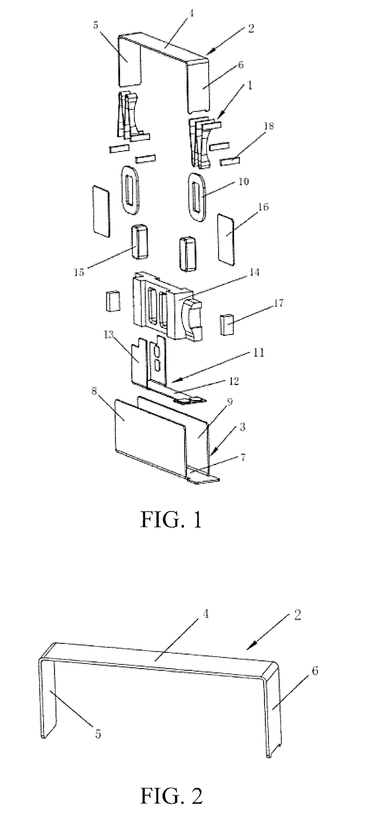
[0022]FIG. 1 is an exploded view of a linear vibrating motor provided by the present application and only shows portions related to the present application to facilitate explanation.

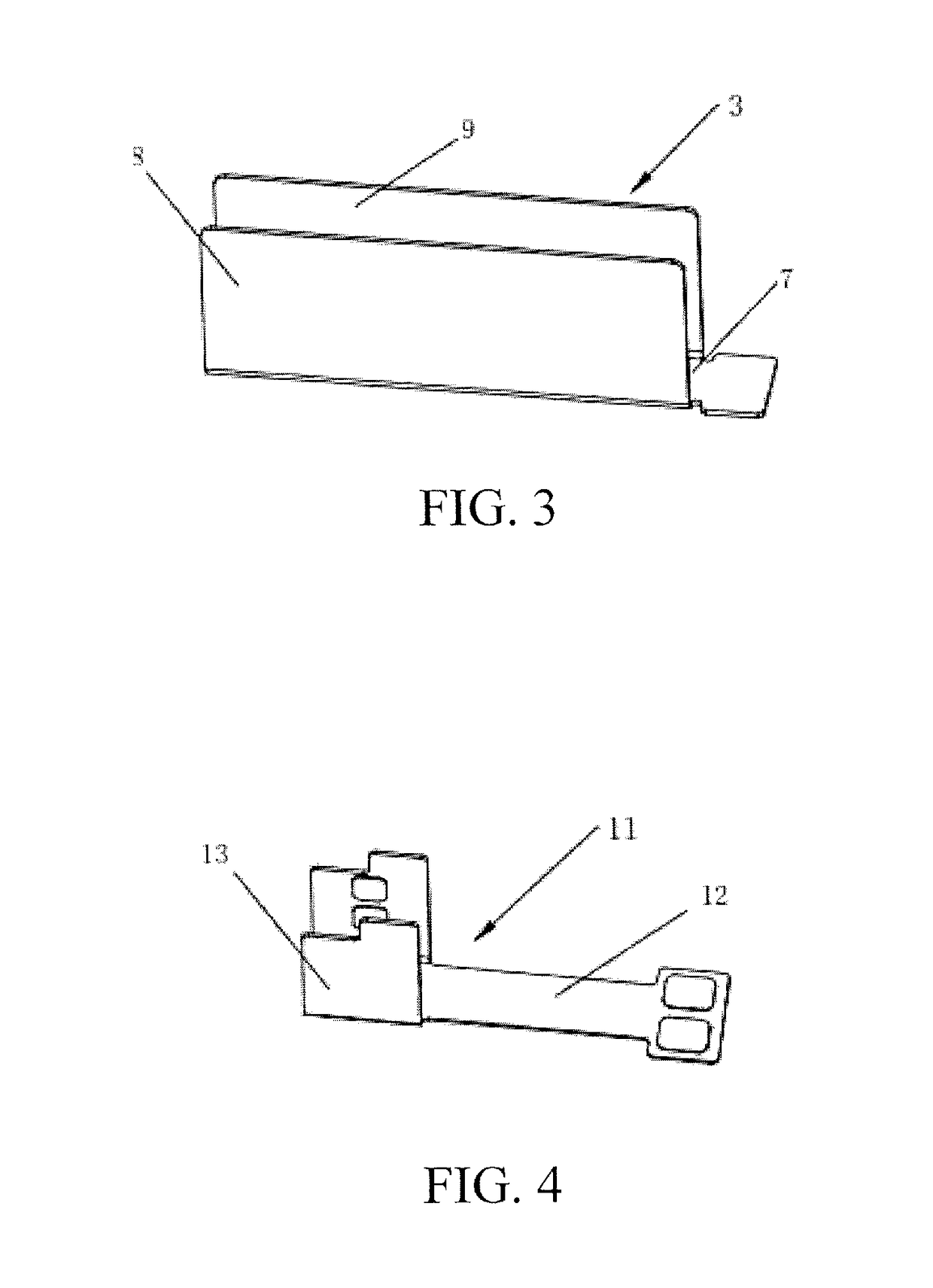
[0023]With reference to FIG. 2 and FIG. 3, the linear vibrating motor comprises a motor housing, a stator, a vibrator and elastic support members 1 through which the vibrator is suspended in the motor housing. Two elastic support members 1 are configured to support the vibrator and to provide elastic restoring forces and are located at two ends of a vibrating direction of the vibrator respectively.

[0024]The motor housing comprises...


PUM


Abstract

The present application relates to the technical field of electronics and provides a linear vibrating motor comprising a motor housing, a stator, a vibrator and an elastic support member for suspending the vibrator in the motor housing and for supporting the vibrator and providing an elastic restoring force; the motor housing comprises a first lateral housing and a second lateral housing; the first lateral housing comprises a first lateral plate, as well as a second lateral plate and a third lateral plate that are disposed at two ends of the first lateral plate respectively; the second lateral housing comprises a fourth lateral plate, as well as a fifth lateral plate and a sixth lateral plate that are disposed at two ends of the fourth lateral plate respectively; and the first lateral housing and the second lateral housing are fastened to form a closed space that accommodates the stator.

Description

FIELD OF THE INVENTION[0001]The present application belongs to the technical field of electronics, and in particular relates to a linear vibrating motor.BACKGROUND OF THE INVENTION[0002]With rapid development of portable consumer electronics at present, more and more consumers favor the electronics that are thinner and have better tactile experience. A linear vibrating motor is generally used as an actuator for the tactile experience and may play a system vibration feedback role. The development direction of thinning of the electronics determines that an elastic support member has to be improved by flattening.[0003]Most linear vibrating motors mainly comprise a motor housing, a vibrator and a stator. The vibrator comprises the elastic support member. The linear vibrating motor realize overall vibration mainly through the elastic support member which is commonly in the format of a spring or an elastic sheet. The elastic support member in the format of the spring or the elastic sheet ...

Claims


Application Information

Patent Timeline
Patent Type & Authority Applications(United States)
IPC IPC(8): H02K33/02
CPCH02K33/02H02K33/16
Inventor ZHU, YUEGUANGLI, YUNCHENG
Owner GOERTEK INC
Why Eureka
Try Eureka