Holder for a tool for material-removing machining, in particular for a longitudinal turning tool

a technology for turning tools and tools, which is applied in the direction of tool holders, turning machines, turning apparatus, etc., can solve the problems of over-long setup times, difficult cutting insert changes, and limited access to the fastening means to be released (mainly screws)

Active Publication Date: 2019-03-21
HARTMETALL WERKZEUGFAB PAUL HORN
View PDF0 Cites 4 Cited by
  • Summary
  • Abstract
  • Description
  • Claims
  • Application Information

AI Technical Summary

Benefits of technology

[0008]It is an object to provide a holder for a tool of the above-mentioned type where it is possible to be able to fasten the cutting insert on the holder in as simple a manner as possible even in tight installation situations. In particular, the structural design for tightening and releasing the cutting insert shall be designed in an alternative manner compared to the aforementioned solutions of the prior art.

Problems solved by technology

When said tool holders are occupied with exchangeable cutting inserts, the cutting insert change is frequently difficult as, in the vast majority of cases, access to the fastening means to be released (mainly screws) is very limited.
This is laborious and results in overly long setup times.

Method used


Image

  • Holder for a tool for material-removing machining, in particular for a longitudinal turning tool
  • Holder for a tool for material-removing machining, in particular for a longitudinal turning tool
  • Holder for a tool for material-removing machining, in particular for a longitudinal turning tool

Examples


Embodiment Construction

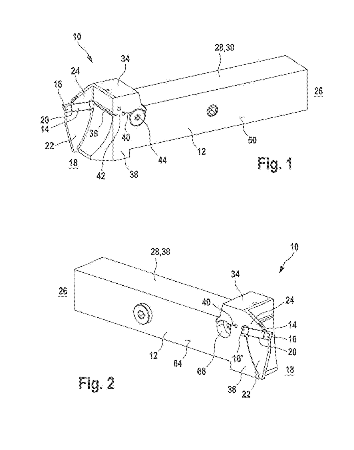
[0042]FIGS. 1 and 2 show perspective views of an exemplary embodiment of the tool from different sides. The tool is designated therein as a whole by way of the reference numeral 10.

[0043]The tool 10 comprises a holder 12, which is frequently also designated as tool holder 12, as well as a cutting insert 14. The cutting insert 14 is releasably fastened on the holder 12, that is to say is not a fixed component part of the holder 12. The holder 12 is preferably produced from steel. The cutting insert 14, in contrast, is preferably produced from hard metal. The cutting insert 14 is preferably a so-called indexable cutting insert which comprises two identical cutting heads 16 or 16′ according to the exemplary embodiment shown in FIGS. 1 and 2, each of the two cutting heads comprising one or multiple cutting edges, by way of which the workpiece is machined so as to remove material when the tool 10 is used. It is obvious, however, that cutting inserts with only one cutting head 16 or with ...


PUM


Abstract

A holder for a tool for machining a workpiece, wherein the holder comprises a cutting insert receptacle in the region of its front end for receiving a cutting insert and a clamping portion in the region of its opposite rear end for clamping the holder in a machine tool. The cutting insert receptacle comprises an upper and a lower clamping jaw, wherein the holder comprises an upper part on which the upper clamping jaw is arranged, and a lower part on which the lower clamping jaw is arranged. The upper and the lower parts are connected together exclusively by means of a web which extends between a first and a second separating slit, wherein the two separating slits extend between the upper part and the lower part of the holder and are arranged on opposite sides of the web such that the upper part is pivotable relative to the lower part via the web in the manner of a rocker. The first separating slit extends in a front holder region between the cutting insert receptacle and the web. The second separating slit extends in a central holder region between the web and the clamping portion. The holder further comprises an actuating means which cooperates with the upper part in the central holder region and is configured to spread the second separating slit in order to move the upper clamping jaw toward the lower clamping jaw and to clamp the cutting insert between the upper and the lower clamping jaws.

Description

CROSS REFERENCE TO RELATED APPLICATIONS[0001]This application is a continuation of international patent application PCT / EP2017 / 061942, filed on May 18, 2017 designating the U.S., which international patent application has been published in German language and claims priority from German patent application DE 10 2016 109 327.0, filed on May 20, 2016. The entire contents of these priority applications are incorporated herein by reference.BACKGROUND OF THE INVENTION[0002]This disclosure relates to a holder for a tool for machining a workpiece. This disclosure further relates to a tool having such a holder and a cutting insert which is exchangeably fixable thereon. The tool according to the present disclosure relates in particular to a turning tool, preferably to a so-called longitudinal turning tool.[0003]An exemplary tool holder for a turning tool is known from EP 2 282 859 B1.[0004]Turning tools of this type mostly consist of a substantially bar-shaped holder produced from steel and ...

Claims


Application Information

Patent Timeline
Patent Type & Authority Applications(United States)
IPC IPC(8): B23B27/04B23B29/04
CPCB23B27/04B23B29/043B23B2205/02B23B2205/04B23B27/10
Inventor NOUREDDINE, HASSAN
Owner HARTMETALL WERKZEUGFAB PAUL HORN
Why Eureka
Try Eureka