Bearing assembly

a bearing and assembly technology, applied in the direction of bearing unit rigid support, liquid fuel engines, machines/engines, etc., can solve the problems of difficult design of rotors and stators for stable operation across the range of operating conditions, compressors may experience rotating stalls, variable stator vane bushes are subject to wear, etc., and achieve the effect of prolonging the length of the sha

Active Publication Date: 2019-03-21
ROLLS ROYCE PLC
View PDF4 Cites 0 Cited by
  • Summary
  • Abstract
  • Description
  • Claims
  • Application Information

AI Technical Summary

Benefits of technology

[0013]The second bush may be positioned adjacent the end of the shaft. The second bush may extend beyond the end of the shaft. The second bush may be positioned such that it effectively extends the length of the shaft.

Problems solved by technology

However, especially as the operating speeds and pressure ratios of compressors are increased, it becomes harder to design the rotors and stators for stable operation across the range of operating conditions.
For example, at off-design conditions, such as lower speed operation, the compressor may experience rotating stall.
Variable stator vane bushes are subject to wear due to the bearing forces and rotation.

Method used


Image

  • Bearing assembly
  • Bearing assembly
  • Bearing assembly

Examples


Embodiment Construction

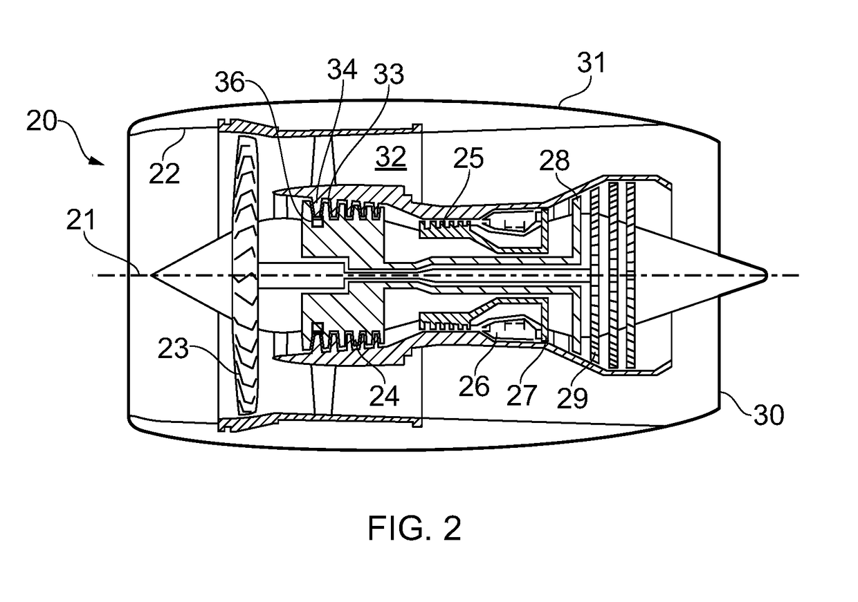
[0041]With reference to FIG. 2, a gas turbine engine is generally indicated at 20, having a principal and rotational axis 21. The engine 20 comprises, in axial flow series, an air intake 22, a propulsive fan 23, an intermediate pressure compressor 24, a high-pressure compressor 25, combustion equipment 26, a high-pressure turbine 27, an intermediate pressure turbine 28, a low-pressure turbine 29 and an exhaust nozzle 30. A nacelle 31 generally surrounds the engine 20 and defines both the intake 22 and the exhaust nozzle 30.

[0042]The gas turbine engine 20 works in the conventional manner so that air entering the intake 22 is accelerated by the fan 23 to produce two air flows: a first air flow into the intermediate pressure compressor 24 and a second air flow which passes through a bypass duct 32 to provide propulsive thrust. The intermediate pressure compressor 24 compresses the air flow directed into it before delivering that air to the high pressure compressor 25 where further comp...


PUM


Abstract

A bearing arrangement comprising a shaft with a recess in its end, a bearing housing, an annular first bush comprising an inner first portion and an inner second portion and a second bush that engages the recess of the shaft. The first bush bears against the bearing housing. The shaft engages the inner first portion of the first bush. The second bush engages the inner second portion of the first bush.

Description

CROSS-REFERENCE TO RELATED APPLICATIONS[0001]This application is based upon and claims the benefit of priority from British Patent Application Number 1715165.5 filed 20 Sep. 2017, the entire contents of which are incorporated by reference.BACKGROUNDTechnical Field[0002]The present disclosure concerns a bearing arrangement, a bearing assembly, a set of variable stator vanes for a gas turbine engine and a method of manufacturing a set of variable stator vanes.Description of the Related Art[0003]Gas turbine engines comprise compressors that impart energy to the air flowing through the engine. Compressors may comprise rotors and stators. The stators are used to reduce swirl and achieve a rise in static pressure. However, especially as the operating speeds and pressure ratios of compressors are increased, it becomes harder to design the rotors and stators for stable operation across the range of operating conditions. For example, at off-design conditions, such as lower speed operation, t...

Claims


Application Information

Patent Timeline
Patent Type & Authority Applications(United States)
IPC IPC(8): F16C33/08F01D17/16
CPCF16C33/08F01D17/162F04D29/563F16C43/02F05D2240/50F16C2360/23F16C35/02F16C17/02
Inventor SCOTHERN, DAVID P.
Owner ROLLS ROYCE PLC
Why Eureka
Try Eureka