Vent for exhaust system

a technology for exhaust systems and vents, applied in space heating and ventilation details, lighting and heating apparatuses, heating types, etc., can solve problems such as motor vibration, exhaust system performance grey area, exhaust system noisy, etc., and achieve the effect of reducing the ingress of foreign objects

Inactive Publication Date: 2019-03-21
DALZARA PTY LTD
View PDF10 Cites 2 Cited by
  • Summary
  • Abstract
  • Description
  • Claims
  • Application Information

AI Technical Summary

Benefits of technology

[0016]The outlet may be covered with a screen for allowing exhaust to be expelled from the vent while minimising the ingress of foreign articles to the vent.
[0017]The screen may be constructed of cinder mesh for the prevention of ingress of embers in a fire situation.

Problems solved by technology

The performance of these vents has been a grey area in the industry for some time, as the outlet in the vent was not designed for the high volume of air produced by the latest exhaust systems available today.
There are problems with back pressure caused by the restriction of the mushroom caps, thereby resulting in the exhaust system becoming noisy, motor vibration and excessive wear due to the strain of the exhaust motor trying to push the air through a restricted vent.
Further, mushroom vents are cheaply manufactured, look undesirable and often leak due to ineffective installation.
As exhaust blows directly down onto the roof from the mushroom cap, staining of the roof is caused, especially from kitchen rangehood exhaust, where odours, cooking vapours and fine molecules of fat are exhausted.

Method used


Image

  • Vent for exhaust system
  • Vent for exhaust system
  • Vent for exhaust system

Examples


Embodiment Construction

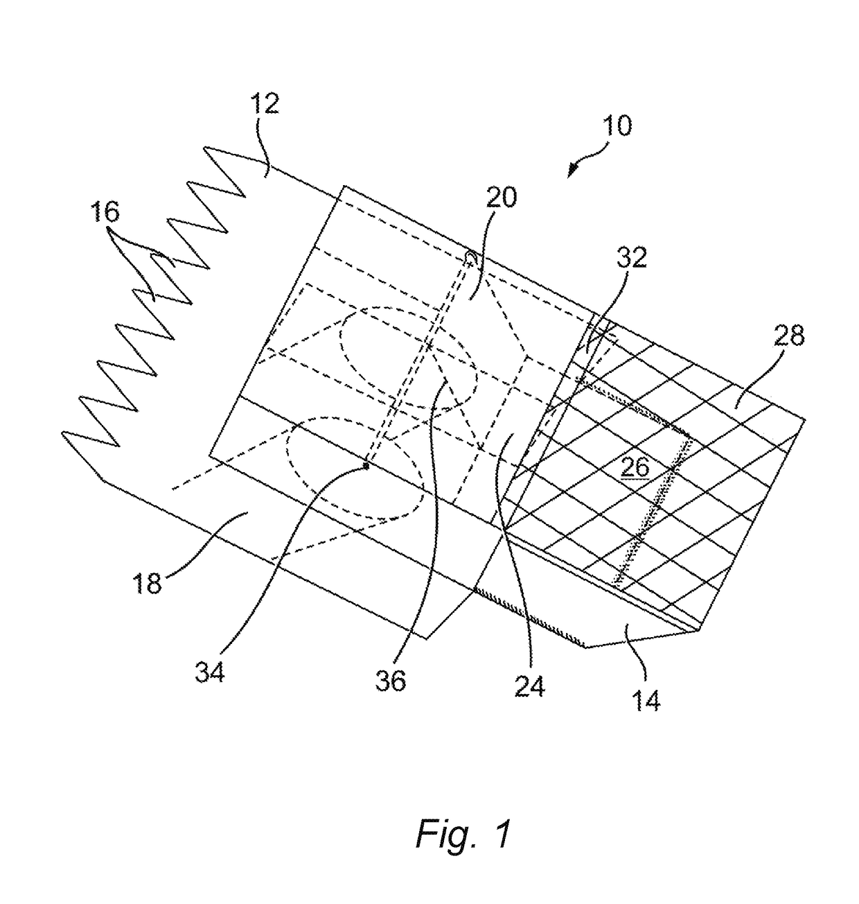
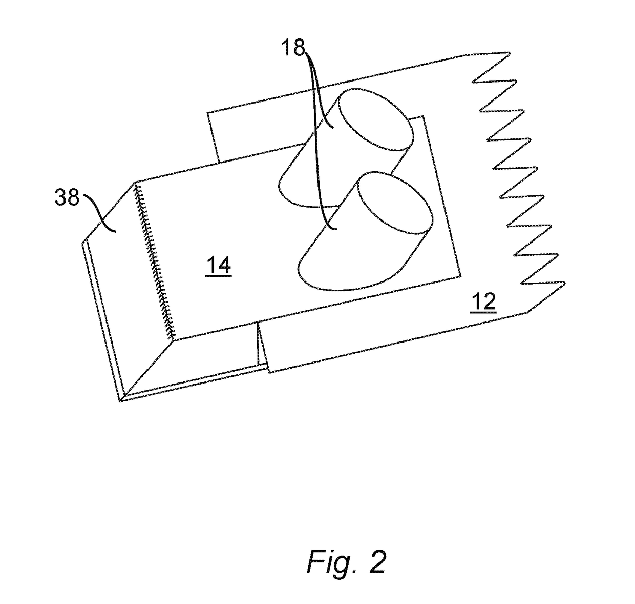
[0030]Referring to the Figures, there is shown an apparatus for improved roof venting for exhaust, generally indicated by reference numeral 10. As best seen in FIG. 1, the exhaust roof vent 10 comprises a shroud 12 and box 14 forming a shell of the vent 10. It is preferred that the shroud 12 and box 14 are constructed from COLORBOND® steel to complement steel-roofed buildings, for example, and from 0.55 mm galvanised tin to complement tiled roofs or walls of other materials upon which the vent 10 is mounted. Each of the shroud 12 and box 14 are preferably formed of a solitary piece punched from sheet material, then folded and fixed into its finished shape.

[0031]The shroud 12 comprises fingers 16 in an end distal from the box 14 when the vent 10 is assembled. The fingers 16 complement the corrugations in COLORBOND® steel so as to provide a snug connection between the shroud and the roof for adequate weather proofing.

[0032]In the case of mounting on material other than COLORBOND® stee...


PUM


Abstract

A vent for venting of exhaust from a building comprising at least one inlet for receiving the exhaust from the building into the vent; at least one valve for assisting in maintaining the unidirectional movement of exhaust from inside to outside the building; and an outlet for allowing the release of the exhaust from the vent; wherein the inlet meets the vent at a forward angle such that the exhaust flows towards the outlet and acts to reduce friction of the exhaust against the vent.

Description

FIELD OF INVENTION[0001]The present invention relates to a system and apparatus for an improved vent for building exhaust.BACKGROUND ART[0002]In order to provide a vent between the interior and exterior of a building, the building industry has been using standard mushroom vents on building roofs for decades. These roof vents were designed for standard ceiling fans commonly used in bathroom, laundries, toilets and kitchens.[0003]The performance of these vents has been a grey area in the industry for some time, as the outlet in the vent was not designed for the high volume of air produced by the latest exhaust systems available today. There are problems with back pressure caused by the restriction of the mushroom caps, thereby resulting in the exhaust system becoming noisy, motor vibration and excessive wear due to the strain of the exhaust motor trying to push the air through a restricted vent.[0004]Further, mushroom vents are cheaply manufactured, look undesirable and often leak due...

Claims


Application Information

Patent Timeline
Patent Type & Authority Applications(United States)
IPC IPC(8): F24F13/14F24F13/02F24F13/28
CPCF24F13/1426F24F13/02F24F13/28F24F2013/1466F24F13/1486
Inventor DALY, TIMOTHY
Owner DALZARA PTY LTD
Why Eureka
Try Eureka