Driveshaft for the gearbox of auxiliary machines of a turbojet engine

a turbojet engine and gearbox technology, applied in machines/engines, packaging, packaging, etc., can solve the problems of reducing the driving efficiency of the shaft, and achieve the effect of reducing the stacking of tolerances, reducing the amount of oil supplied, and improving the positioning of the shaft lin

Active Publication Date: 2017-10-24
SN DETUDE & DE CONSTR DE MOTEURS DAVIATION S N E C M A
View PDF10 Cites 3 Cited by
  • Summary
  • Abstract
  • Description
  • Claims
  • Application Information

AI Technical Summary

Benefits of technology

[0013]According to one feature of the invention, this further comprises a lubrication-oil injection device arranged to inject lubrication oil in the region of a plane transversely passing through the plurality of splines and the plurality of rolling bearings. This makes it possible to optimise the supply of oil, thus preventing the oil from producing an unbalance or a mass which would unbalance the shaft in its rotation, if it were transported in a conventional manner via the shafts.
[0014]According to another feature of the invention, the turbojet engine further comprises an outer race for the intermediate bearing, which race is centred in the casing. This improves the positioning of the shaft line while minimising the stacking-up of tolerances. This also makes it possible to close the oil enclosure formed by the casing and helps to seal it by compressing the seal mounted in the neck of the casing. This also makes it possible to centre and seal the secondary sleeve.

Problems solved by technology

The deformations caused by these aerodynamic forces on the radial arm result in a first misalignment of the driveshaft in the region of the connection between the first shaft element and the second shaft element and a second misalignment of the driveshaft in the region of the intermediate bearing.
These misalignments thus appear in different zones and produce an unbalance and vibrations of the driveshaft in the radial arm, resulting in particular in a moment in the region of the rolling bearings of the intermediate bearing, which reduces the driving efficiency of the shaft.

Method used


Image

  • Driveshaft for the gearbox of auxiliary machines of a turbojet engine
  • Driveshaft for the gearbox of auxiliary machines of a turbojet engine
  • Driveshaft for the gearbox of auxiliary machines of a turbojet engine

Examples


Embodiment Construction

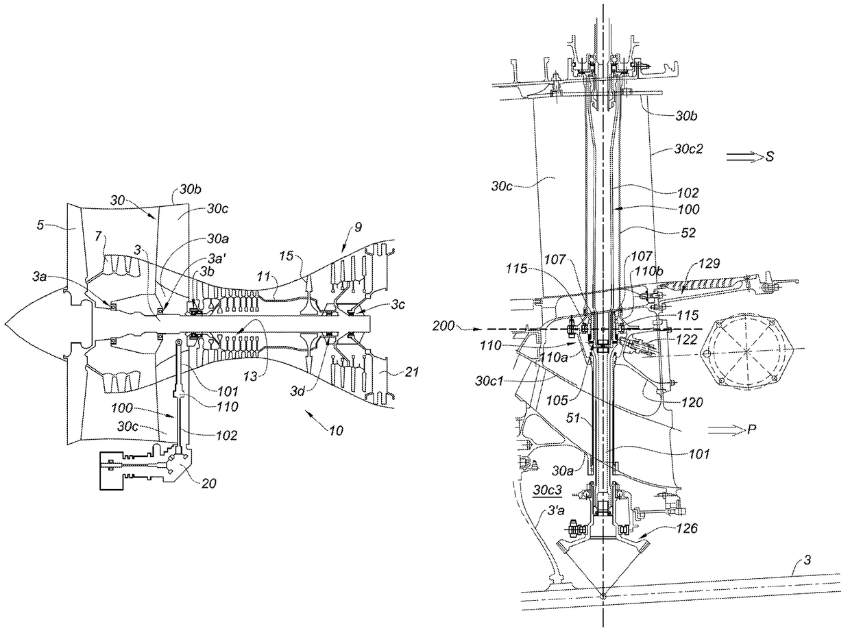
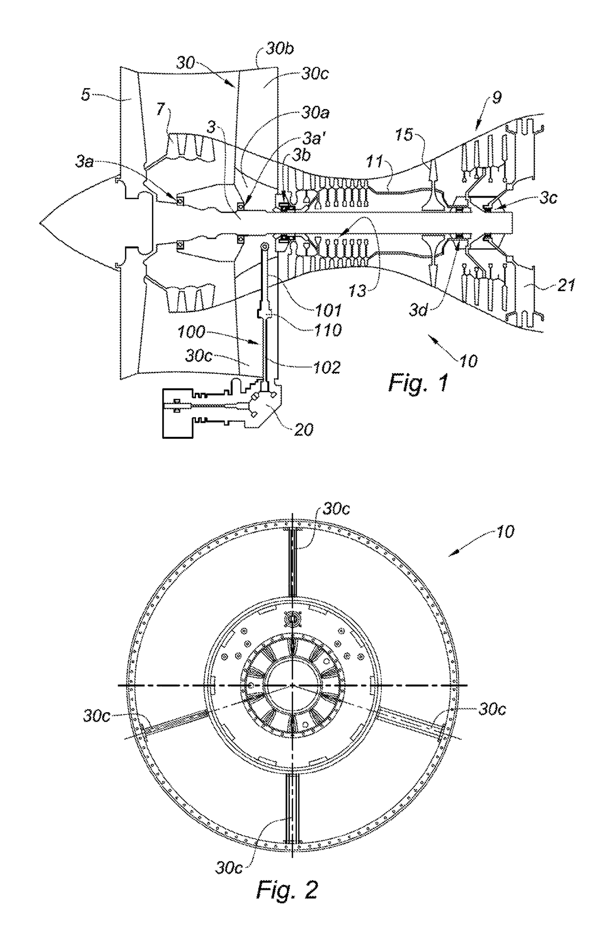
[0022]FIG. 1 schematically shows a twin-spool turbofan engine 10 and the various main components thereof. Said engine comprises a first shaft 3 connecting, on the left-hand side in the figure, a fan rotor 5 and the first compressor stages 7 to the low-pressure turbine 9; the assembly forms the low-pressure or LP spool. Coaxial with the first shaft, a second shaft 11 in the form of a drum connects the high-pressure stages 13 of the compressor to the high-pressure turbine 15; the assembly forms the high-pressure or HP spool with the combustion chamber (not shown). The shaft 3 is supported upstream by the bearings 3a and 3a′ mounted on the casing 30 which is referred to as the intermediate casing, and downstream by the bearing 3c mounted on the exhaust casing 21. The HP shaft is supported here by the bearing 3b of the intermediate casing 30 and at the rear of the shaft 3 via the inter-shaft bearing 3d.

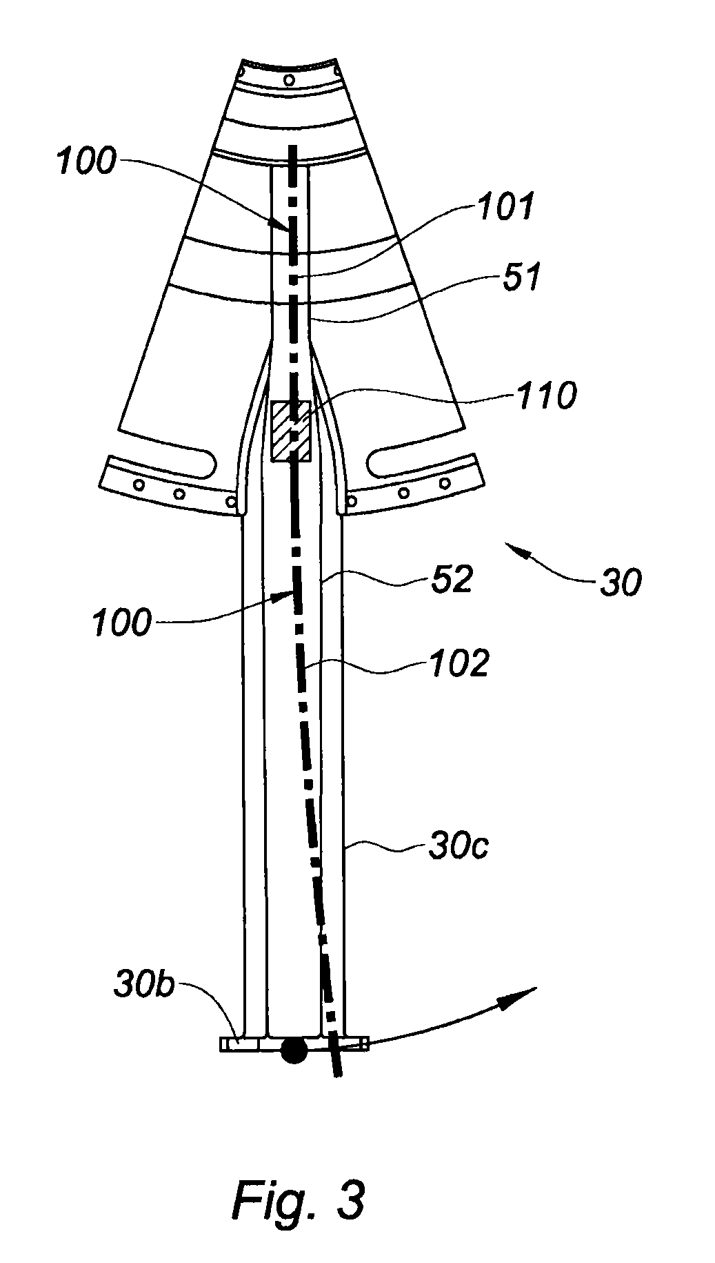
[0023]The intermediate casing 30 is made up of a hub 30a supporting the bearings 3a,...


PUM


Abstract

A turbojet engine including an intermediate casing including radial arms and a driveshaft for a gearbox for auxiliary machines of the turbojet engine, the driveshaft mounted in a radial arm, the radial arm including an intermediate bearing supporting the driveshaft, the intermediate bearing including plural rolling bearings supporting the driveshaft, the driveshaft including a first shaft element connected at one end to a mechanism providing mechanical transmission to an engine shaft of the turbojet engine, and a second shaft element connected at one end to a mechanism providing mechanical transmission to the box. The first shaft element and the second shaft element are linked by a connection including plural splines. A single plane transversely passes through the plural splines and the plural rolling bearings.

Description

FIELD OF INVENTION[0001]The present invention relates to the field of multi-spool and multi-flow aircraft turbojet engines. It is directed to a specific configuration of a driveshaft in a radial arm of an intermediate casing of such a turbojet engine.BACKGROUND OF THE INVENTION[0002]For driving auxiliary machines mounted on the turbojet engine, such as electric generators or oil or fuel pumps, which are required for operation of the turbojet engine or of the aircraft on which it is mounted, the required power is generally drawn from the main shaft. A twin-spool turbojet engine comprises two coaxial shafts: one, a low-pressure or LP shaft, connecting the low-pressure compressor to the low-pressure turbine, together forming the LP spool; the other, a high-pressure or HP shaft, connecting the high-pressure compressor to the high-pressure turbine, together forming the HP spool. In the case of such an engine, the power is generally transmitted to the auxiliaries by a radial arm, accommod...

Claims


Application Information

Patent Timeline
Patent Type & Authority Patents(United States)
IPC IPC(8): B60K25/06F02C7/32F02C7/36F02K3/06
CPCB60K25/06F02C7/32F02K3/06F02C7/36F05D2220/50
Inventor BRAULT, MICHEL GILBERT ROLANDSERVANT, REGIS EUGENE HENRI
Owner SN DETUDE & DE CONSTR DE MOTEURS DAVIATION S N E C M A
Why Eureka
Try Eureka