
System and method for operating a grid controlled water heater

Active Publication Date: 2019-03-21
A O SMITH
View PDF0 Cites 2 Cited by
  • Summary
  • Abstract
  • Description
  • Claims
  • Application Information

AI Technical Summary

Benefits of technology

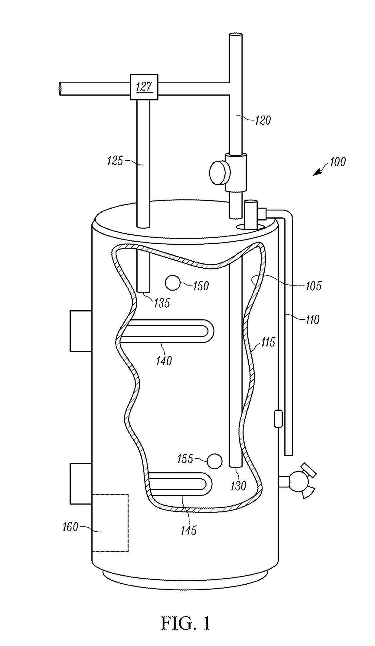
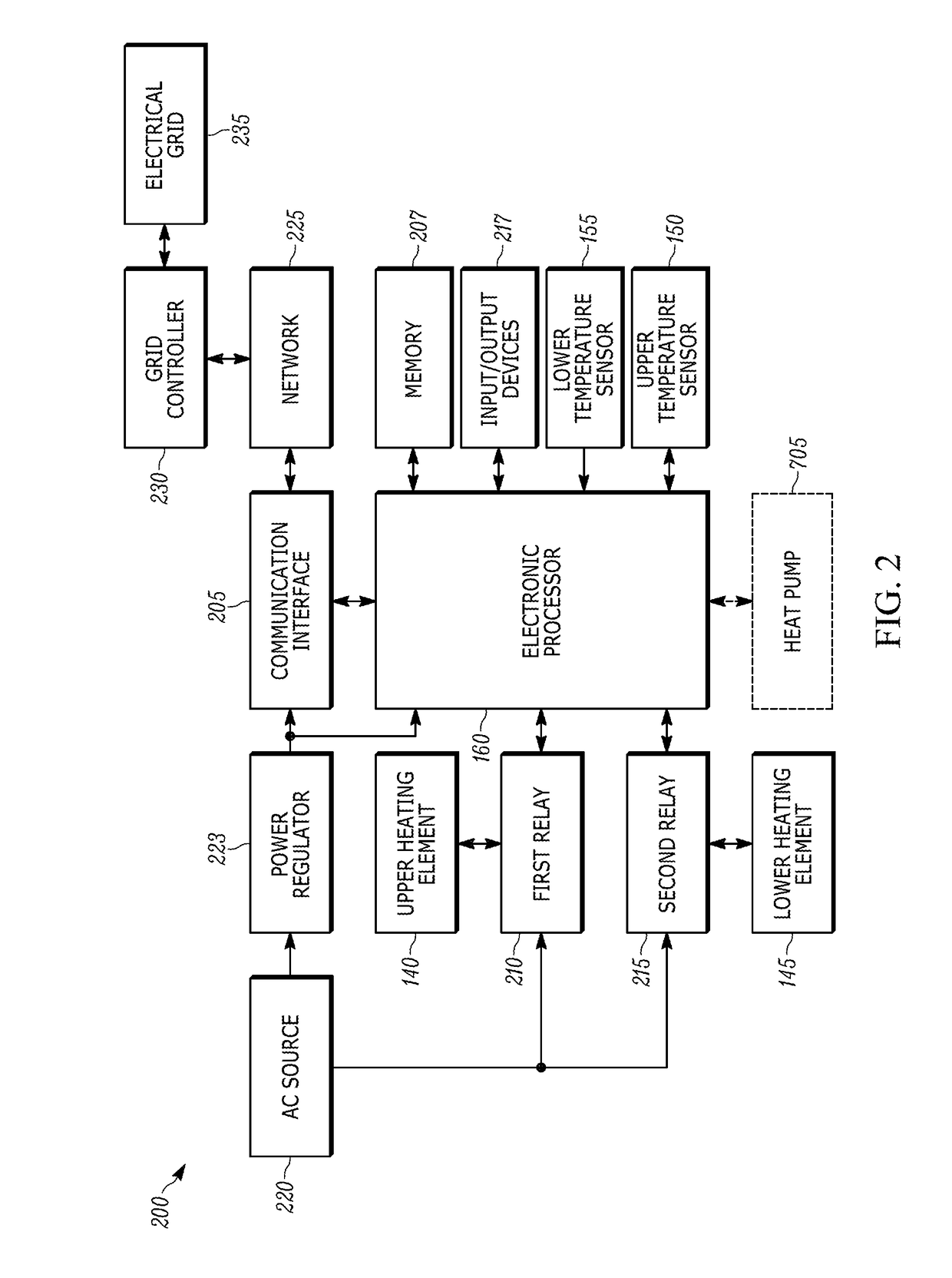
This patent is about a water heater system that receives electrical power from an electrical grid and uses a control circuit to regulate the heating of water in the tank. The system includes an upper and lower heating element and sensors to measure water temperature in the tank. The control circuit monitors the water temperature and can adjust the heating elements accordingly. This allows the system to conserve energy and provide hot water when needed. The technical effect of this patent is to provide a more efficient and effective water heating system that is adjusted based on real-time demand and water temperature, resulting in cost savings and improved user experience.

Problems solved by technology

For example, the price of electricity increases during peak hours, and decreases during off-peak hours.
Furthermore, participating in programs that control the heating elements based on the electrical energy demand may, in some instances, reduce the amount of hot water that is available to the user (e.g., to conserve energy).
In such instances, the user may not have sufficient hot water available for comfortable use.
While some users may be able to tolerate these instances, other users may find the occasional lack of hot water unacceptable.
However, at time T25, a large water draw causes the lower temperature to decrease rapidly.
The consecutive operation of the lower heating element 145 in the previous and present heating cycles indicates that an insufficient amount of energy is being “shed” by the water heater 100 resulting in a waste of energy resources.
However, there may be situations when operating in the reduced mode causes the user to run out of hot water.

Method used


Image

  • System and method for operating a grid controlled water heater
  • System and method for operating a grid controlled water heater
  • System and method for operating a grid controlled water heater

Examples


Embodiment Construction

[0027]Before any embodiments of the invention are explained in detail, it is to be understood that the invention is not limited in its application to the details of construction and the arrangement of components set forth in the following description or illustrated in the following drawings. The invention is capable of other embodiments and of being practiced or of being carried out in various ways. Also, it is to be understood that the phraseology and terminology used herein is for the purpose of description and should not be regarded as limiting. The use of “including,”“comprising,” or “having” and variations thereof herein is meant to encompass the items listed thereafter and equivalents thereof as well as additional items. Unless specified or limited otherwise, the terms “mounted,”“connected,”“supported,” and “coupled” and variations thereof are used broadly and encompass both direct and indirect mountings, connections, supports, and couplings. Further, “connected” and “coupled”...


PUM


Abstract

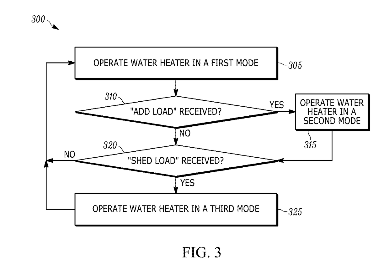
Methods and systems for water heater system receiving electrical power from an electrical grid. The system includes an electronic processor configured to monitor an average water temperature of the water within a water tank of the system based on a first and second signal from a upper and lower temperature sensor, operate a upper heating element heating an upper portion of the tank and a lower heating element heating a lower portion of the tank in a first operation mode, receiving, via a transceiver, either an add load command or a shed load command from a grid controller, operating the upper heating element and lower heating element in a second mode in response to receiving the add load command, and operating the upper heating element and lower heating element in a third mode in response to receiving the shed load command.

Description

RELATED APPLICATIONS[0001]This application claims the benefit to U.S. Provisional Patent Application No. 62 / 560,348, filed on Sep. 19, 2017, the entire contents of which are incorporated herein by reference.FIELD OF INVENTION[0002]Embodiments relate to water heaters.SUMMARY[0003]Electric and heat pump operated water heaters use electrical energy to heat the water located inside a water tank to maintain the water within a temperature range. The electrical energy may come from a power source such as a grid, or a power grid, for example but not limited to, an energy company power grid or a home power grid including solar panels, windmills, or other energy sources. The power grid distributes electrical energy to balance supply and demand at any specific time within a specific area. The demand for electrical energy from the power grid varies with, for example, time of day, seasons, geographical area, usage, and other factors. The price for the electricity delivered by the power grid vari...

Claims


Application Information

Patent Timeline
IPC IPC(8): F24H9/20F24H1/18F24H1/20
CPCF24H9/2021F24H1/185F24H1/202F24H2250/02G05D23/1931F24H15/156F24H15/45F24H15/395F24H15/375F24H15/168F24H15/277F24H15/281F24H15/225F24H15/37F24H15/407F24H15/175F24H15/421
Inventor BRANECKY, BRIAN THOMASLEE, YONGGONDIMBLE, KEDAR D.
Owner A O SMITH
Learn More